Line routing device

a line routing and cable technology, applied in the direction of coupling device connection, extensible conductor, conductor, etc., can solve the problem of very low assembly effort and achieve the effect of permanent secure and reliable operation and simple construction

Inactive Publication Date: 2011-03-22
LEONI BORDNETZ SYST
View PDF15 Cites 17 Cited by
  • Summary
  • Abstract
  • Description
  • Claims
  • Application Information

AI Technical Summary

Benefits of technology

[0006]It is accordingly an object of the invention to provide a line routing device, which overcomes the hereinafore-mentioned disadvantages of the heretofore-known devices of this general type and which can be used for routing a cable between two components that can move relative to one another, in particular for linking a motor-vehicle sliding door to a motor-vehicle power supply system, with the line routing device having a simple construction and ensuring permanently secure and reliable operation.
[0007]With the foregoing and other objects in view there is provided, in accordance with the invention, a line routing device comprising a housing having a movement opening which extends in longitudinal direction and in which a movement element is mounted in such a way that it can move. An electrical cable is attached to the movement element and is provided for an electrical connection between the two components which can move relative to one another. The cable is routed in the direction of an outlet opening within the housing. The cable is routed along a spring strip which is bent in a U-shape, in particular a spring steel strip, which is attached at one end to the movement element and at the other end to the housing in the area of the outlet opening. A strip composed of plastic with appropriate spring characteristics is used as an alternative to a spring steel strip. A defined line routing path is formed by the spring strip, because of the spring strip and its attachment to the movement element, during a relative movement between the two components and a movement associated therewith of the movement element in the movement opening. The spring strip which is bent in a U-shape changes its geometry during the movement in such a way that the U-limbs are moved with respect to one another. The cable, which rests loosely on the spring strip or else is fixed, is routed in a defined manner, independently of the respective position. The use of a spring strip furthermore results in a very simple and therefore cost-effective construction, which ensures permanently reliable operation.
[0008]The housing is preferably formed from a base part and a cover part, and the movement element as well as the spring strip can be inserted into the housing when the cover part is removed. This allows quick and simple fitting. In particular, provision is made in this case for the cable together with the movement element and the spring strip, possibly as well as interfaces that are attached at the end, for example plug connectors, to be inserted as a prefabricated cable harness unit into the housing, which then just needs to be closed. In this case in particular, the amount of assembly effort is therefore very low.
[0010]The mounting aid in this case is preferably in the form of a holding tab which is integrally formed on the base part and engages over the spring strip in the mounting position. Furthermore, the mounting position is preferably a movement limit position, in which the movement element is located in one of the two limit positions. This serves to simplify the assembly process, since the mounting position is defined in a fixed manner for the prefabricated cable harness.
[0013]Provision is preferably also made for the movement element to include two subelements, specifically a sliding body which can slide along within the movement opening, and a rotating body which is mounted in such a way that it can rotate relative thereto. The cable is passed through this rotating body. The capability of the rotating body to rotate results in the cable being routed reliably, allowing a compensating rotary movement.
[0016]In one preferred refinement, the entire line routing device is in the form of a prefabricated mounting unit, which just needs to be fitted into the installation space that is provided. In order to provide for connection of the electrical supply, the line routing device has interfaces at both ends of the cable, in particular plugs to form plug connections. For this purpose, the line routing device has a first cable subelement, which is routed from a first cable interface outside the housing to the movement element, as well as a second cable subelement, which is routed within the housing from the movement element to a second interface in the area of the outlet opening. This refinement, as a prefabricated mounting unit with interfaces which are in particular in the form of plug connectors, allows very simple and fast fitting of the entire line routing device, for example in a production line at an automobile manufacturer.

Problems solved by technology

In this case in particular, the amount of assembly effort is therefore very low.

Method used


Image

  • Line routing device
  • Line routing device

Examples


Embodiment Construction

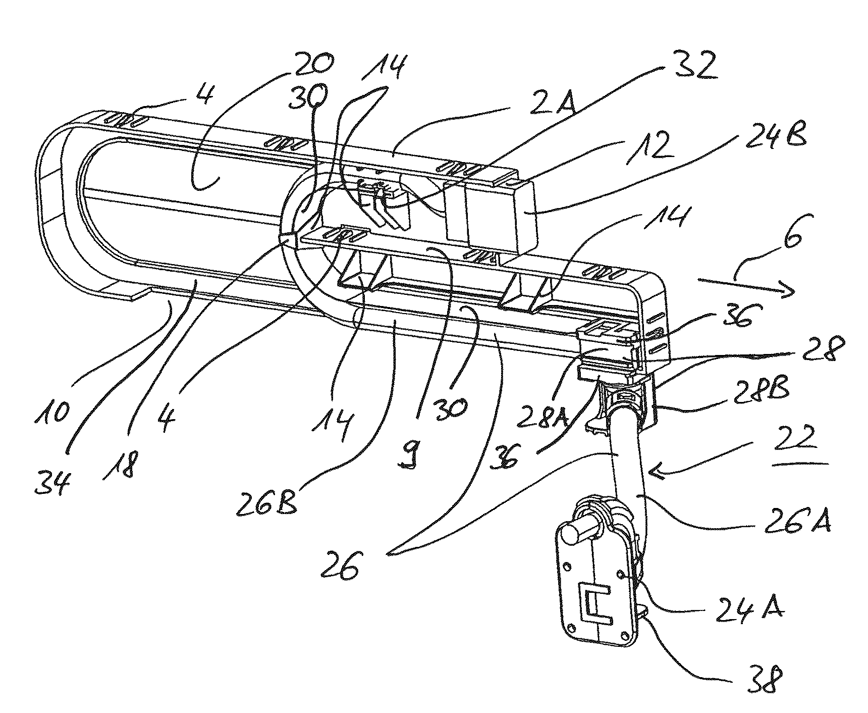
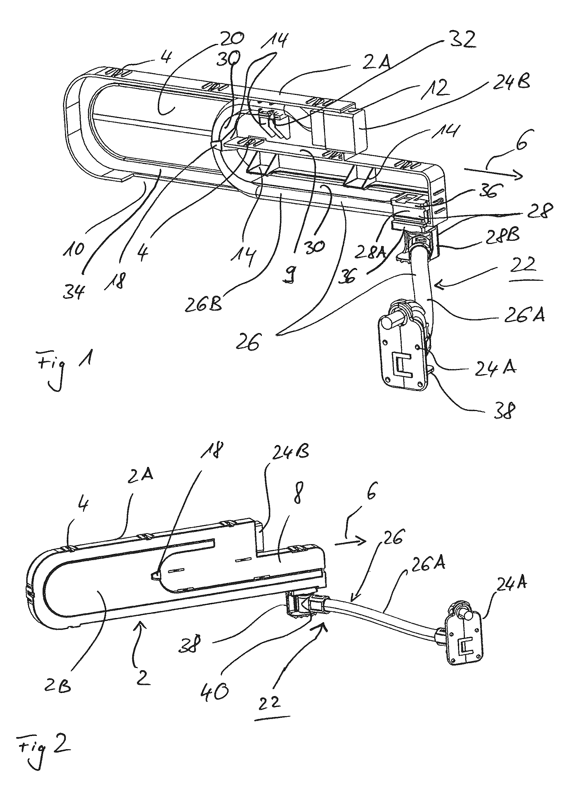
[0022]Referring now in detail to the figures of the drawings as a whole, there is seen a line routing device including a housing 2 which has two parts, namely a base part 2A and a cover part 2B. In the exemplary embodiment, the cover part 2B is detachably attached to the base part 2A through latching connections 4. The housing 2 has an approximately cuboid basic geometry and extends in a longitudinal direction 6. A housing limb 8 is drawn out somewhat further on one of the two sides in the longitudinal direction 6 and has approximately half the width of the housing, in the same way as a recessed subarea. A side wall section of the housing limb 8, which is formed for the recessed subarea, is partially continued as a partition wall 9 within the housing 2.

[0023]A movement opening 10 is formed in a narrow face of the housing limb 8, opposite the partition wall 9, and occupies virtually the entire height of the narrow face. The movement opening 10 is constructed to be open toward the cov...


PUM


Abstract

A line routing device is provided in order to allow simple, reliable electrical linking, in particular of a motor-vehicle sliding door to a vehicle power supply system. The line routing device includes a housing having a movement opening which extends in longitudinal direction and an outlet opening. A movement element is movably mounted in the movement opening and the cable as well as a spring strip, which is bent in a U-shape, are attached to the movement element. The cable is routed along the spring strip to the outlet opening and an end of the spring strip, which is remote from the movement element, is fixed to the housing.

Description

CROSS-REFERENCE TO RELATED APPLICATION[0001]This is a continuation, under 35 U.S.C. §120, of copending International Application No. PCT / EP2008 / 002449, filed Mar. 28, 2008, which designated the United States; this application also claims the priority, under 35 U.S.C. §119, of German Patent Application DE 10 2007 017 286.0, filed Apr. 12, 2007; the prior applications are herewith incorporated by reference in their entirety.BACKGROUND OF THE INVENTIONField of the Invention[0002]The invention relates to a cable or line routing device, in particular for a sliding door in the motor-vehicle field.[0003]A line routing device is often provided for an electrical connection between two components which can move relative to one another. An electrical cable, to which the two components that can move relative to one another are connected, is routed in the line routing device.[0004]In motor-vehicle construction, line routing devices are used, for example, for electrically linking a sliding door t...

Claims


Application Information

Patent Timeline
Patent Type & Authority Patents(United States)
IPC IPC(8): H02G11/00
CPCB60R16/0215E05F15/632H02G11/006E05Y2400/654E05Y2900/531E05F15/655B60J5/06
Inventor PIEH, MARIOFRIEDRICH, NORBERTMEYER, ALEXANDERHEITMEIER, MATTHIAS
Owner LEONI BORDNETZ SYST
Why Eureka
Try Eureka