Method for manufacturing X-ray detector and X-ray detector

a technology of x-ray detector and manufacturing method, which is applied in the direction of radiation intensity measurement, instruments, x/gamma/cosmic radiation measurement, etc., can solve the problems of easy reduction of joint strength between the interface of the protective layer and the member made of a different material, and increase in the production cost of such x-ray detectors

Active Publication Date: 2011-03-22
CANON ELECTRON TUBES & DEVICES CO LTD
View PDF10 Cites 4 Cited by
  • Summary
  • Abstract
  • Description
  • Claims
  • Application Information

AI Technical Summary

Benefits of technology

[0012]An object of the present invention is to provide a method for manufacturing an X-ray detector and the X-ray detector manufactured thereby in which a scintillator layer can be positively protected.
[0013]A method for manufacturing an X-ray detector of the present invention comprises: forming a first protective layer on a surface of a photoelectric conversion substrate on which photoelectric transducers have been provided; forming a scintillator layer on a surface of the first protective layer; and forming a second protective layer composed of the same material as that of the first protective layer so as to cover the surface of the scintillator layer and such that a peripheral part of the second protective layer is allowed to be in close contact with a peripheral part of the first protective layer to seal the scintillator layer between the first protective layer and the second protective layer.
[0015]According to the present invention, the first protective layer is formed on the surface of the photoelectric conversion substrate on which a plurality of the photoelectric transducers have been arrayed, and then, the scintillator layer is formed on the surface of the first protective layer. As a result, corrosion of the photoelectric transducers due to the contact with the scintillator layer can be prevented. Moreover, the second protective layer is formed so as to cover the surface of the scintillator layer and further such that the peripheral part of the second protective layer is allowed to be in close contact with the peripheral part of the first protective layer to seal the scintillator layer between the first protective layer and the second protective layer. Accordingly, the deliquescence of the scintillator layer due to the moisture in the atmospheric air can be prevented. In addition, since the first protective layer is composed of the identical material to that of the second protective layer, degradation in the joint strength as well as a stress due to the difference in coefficients of thermal expansion in the interface of the joint surface of the first protective layer and the second protective layer can be reduced, whereby a closely sealed condition of the scintillator layer can be positively assured so that the scintillator layer can be positively protected.

Problems solved by technology

As a result, there arise problems of degradations in a variety of characteristics and the reliability of an X-ray detector, decrease in the productivity and increase in the production cost of such X-ray detector.
However, since the peripheral part of the protective layer covering the scintillator layer is joined to a circuit board or the like made of a different material, there still remain such problems that a joint strength in the interface of the protective layer and a member made of a different material decreases easily, and further that the protective layer exfoliates due to a stress generated by a difference in coefficients of thermal expansion between the protective layer and the member made of the different material, whereby sealing property of the scintillator layer is damaged.

Method used


Image

  • Method for manufacturing X-ray detector and X-ray detector
  • Method for manufacturing X-ray detector and X-ray detector
  • Method for manufacturing X-ray detector and X-ray detector

Examples


first embodiment

[0031]the invention is illustrated in FIGS. 1, 2 and 3 as well as in FIGS. 4A through 4H.

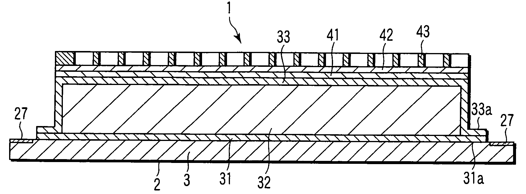
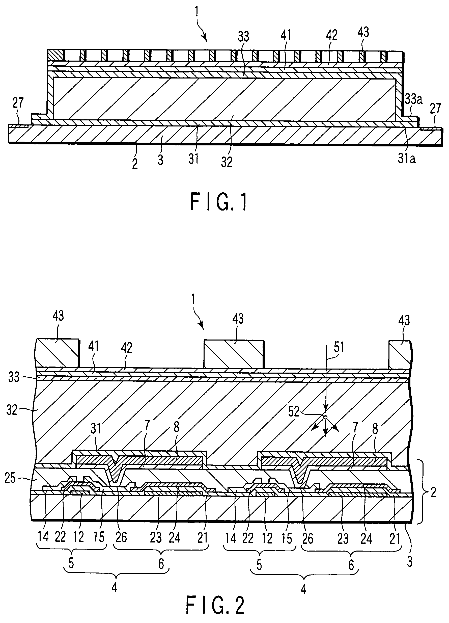
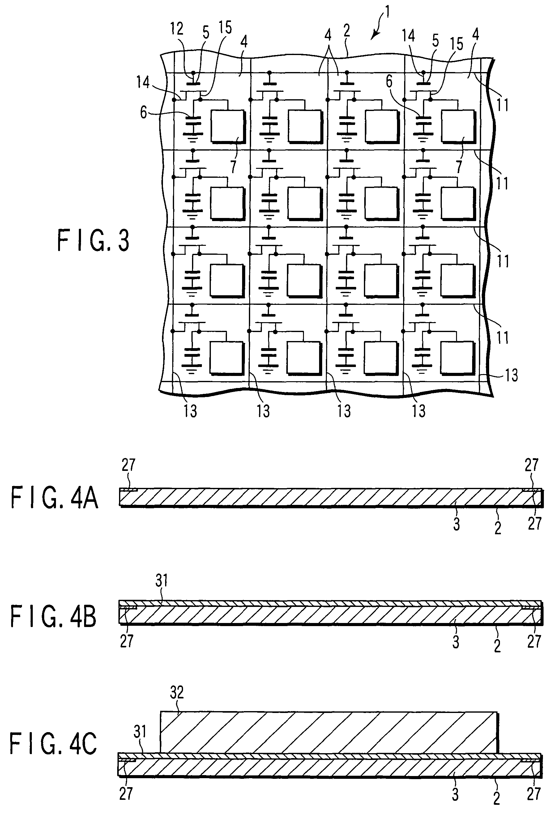
[0032]In FIGS. 1 through 3, reference numeral 1 designates an X-ray detector, and the X-ray detector 1 is an X-ray two-dimensional image detector of the indirect technique. The X-ray detector 1 is provided with a photoelectric conversion substrate 2 serving as an active matrix photoelectric conversion substrate for converting a visible light into electrical signals.

[0033]The photoelectric conversion substrate 2 is provided with a support substrate 3 functioning as an insulating substrate formed from rectangular flat plate-shaped glass and the like having transmittive property. On the surface of the support substrate 3, a plurality of picture elements 4 are two-dimensionally arrayed in a matrix shape, and a thin film transistor (TFT) 5 functioning as a switching element, a capacitor 6 for accumulating electric charge, a picture electrode 7, and a photoelectric transducer 8 such as a photodiode ar...

second embodiment

[0072]Furthermore, the present invention is illustrated in FIG. 5.

[0073]A reflection layer 41 is formed on the surface of a scintillator layer 32, and then, a second protective layer 33 is formed so as to cover the scintillator layer 32 including the reflection layer 41.

[0074]Also in an X-ray detector 1 of the second embodiment having the construction as described above, the same advantageous effect as the X-ray detector 1 of the first embodiment can be obtained.

[0075]Although picture elements 4 are formed two-dimensionally on a photoelectric conversion substrate 2 in a matrix shape, it may be formed one-dimensionally.


PUM


Abstract

A first protective layer is formed on the surface of a photoelectric conversion substrate on which photoelectric transducers have been provided, and then, a scintillator layer is formed thereon, whereby degradation of the photoelectric transducers due to the contact with the scintillator layer is prevented. A second protective layer covering the surface of the scintillator is formed. A peripheral part of the first protective layer is allowed to be in close contact with a peripheral part of the second protective layer to seal the scintillator layer between the first protective layer and the second protective layer, whereby degradation of the scintillator layer due to the moisture in the atmospheric air is prevented.

Description

CROSS-REFERENCE TO RELATED APPLICATIONS[0001]This application is based upon and claims the benefit of priority from prior Japanese Patent Application No. 2005-369494, filed Dec. 22, 2005, the entire contents of which are incorporated herein by reference.BACKGROUND OF THE INVENTION[0002]1. Field of the Invention[0003]The present invention relates to a method for manufacturing an X-ray detector for detecting X-ray and the X-ray detector manufactured thereby.[0004]2. Description of the Related Art[0005]A flat X-ray detector using an active matrix has been attracting attention as a new-generation X-ray diagnostic image detector. In this type of the X-ray detector, when X-ray is irradiated on an object, an X-ray photographed image or a real-time X-ray image of the object is output as digital image signals. Since the X-ray detector is a solid detector, it is extremely expected in terms of image quality performance and stability so that a great amount of research and development has been p...

Claims


Application Information

Patent Timeline
Patent Type & Authority Patents(United States)
IPC IPC(8): G01T1/20
CPCG01T1/2018H01L27/14663H01L27/14685H01L27/14692G01T1/20189G01T1/20185G01T1/20187
Inventor HORIUCHI, HIROSHIAIDA, HIROSHI
Owner CANON ELECTRON TUBES & DEVICES CO LTD
Why Eureka
Try Eureka