Wheel having a controlled pressure and a pressure reservoir

a technology of pressure reservoir and controlled pressure, which is applied in the direction of inflatable tyres, transportation and packaging, and multiple inflatable chambers, etc., can solve the problems that the operating pressure of known devices cannot be precisely adjusted, and the conditions cannot be obtained withou

Inactive Publication Date: 2011-03-22
PIRELLI TYRE SPA
View PDF9 Cites 31 Cited by
  • Summary
  • Abstract
  • Description
  • Claims
  • Application Information

AI Technical Summary

Benefits of technology

[0011]The Applicant realised that known devices do not enable a precise adjustment of the operating pressure of the tyre, which adjustment is particularly important for a tyre suitable for high performance both for two-wheeled and four-wheeled vehicles. In fact, for the vehicle roadholding and handling, above all as far as mixed paths of travel at high speed are concerned, a tyre in excellent conditions is required, which conditions cannot be obtained without a serious control of the operating pressure. Finally, maintaining a correct and constant operating pressure also allows problems of uneven or early wear of the tread band to be avoided.
[0015]To this aim the Applicant could verify that the above discussed problem can be overcome by making at least one valve assembly inserted between a tank of fluid under pressure associated with the rim of a wheel and the tyre mounted on said rim, where at least one valve of said assembly allows communication between the tank and the tyre, said valve being operated by at least another valve of said assembly which is responsive to lowering of the tyre pressure, so that the operating pressure of the tyre can be restored with the desired precision and timeliness.
[0021]It is further to be pointed out that known devices do not allow pressure variation within the tyre to be suitably compensated for, when said variation is due to important temperature variations, in the order of some ten degrees for example. More specifically, in the case of a strong reduction in the external temperature, the inner pressure of each tyre will decrease, since said pressure, as it is well known, is proportional to the absolute temperature in accordance with the gas laws. The Applicant could notice that a pressure restoration to such low temperatures through passage of fluid under pressure (compressed air, for example) from the tank to the tyre, would involve an overpressure during running or, at all events, at the moment the fluid temperature within the tyre should rise again. This overpressure can cause discharge of the previously admitted air to restore the correct operating pressure, thereby reducing the tank independence.
[0026]It will be recognised that in this manner in accordance with the invention, the operating duration of the tank of fluid under pressure is advantageously increased. In fact, fluid admission (air, for example) from the tank to said tyre is substantially inhibited when the tyre pressure decreases due to lowering of the external temperature, so that overpressures in the tyre and / or subsequent fluid discharges due to temperature increases are avoided.

Problems solved by technology

The Applicant realised that known devices do not enable a precise adjustment of the operating pressure of the tyre, which adjustment is particularly important for a tyre suitable for high performance both for two-wheeled and four-wheeled vehicles.
In fact, for the vehicle roadholding and handling, above all as far as mixed paths of travel at high speed are concerned, a tyre in excellent conditions is required, which conditions cannot be obtained without a serious control of the operating pressure.

Method used


Image

  • Wheel having a controlled pressure and a pressure reservoir
  • Wheel having a controlled pressure and a pressure reservoir
  • Wheel having a controlled pressure and a pressure reservoir

Examples


Embodiment Construction

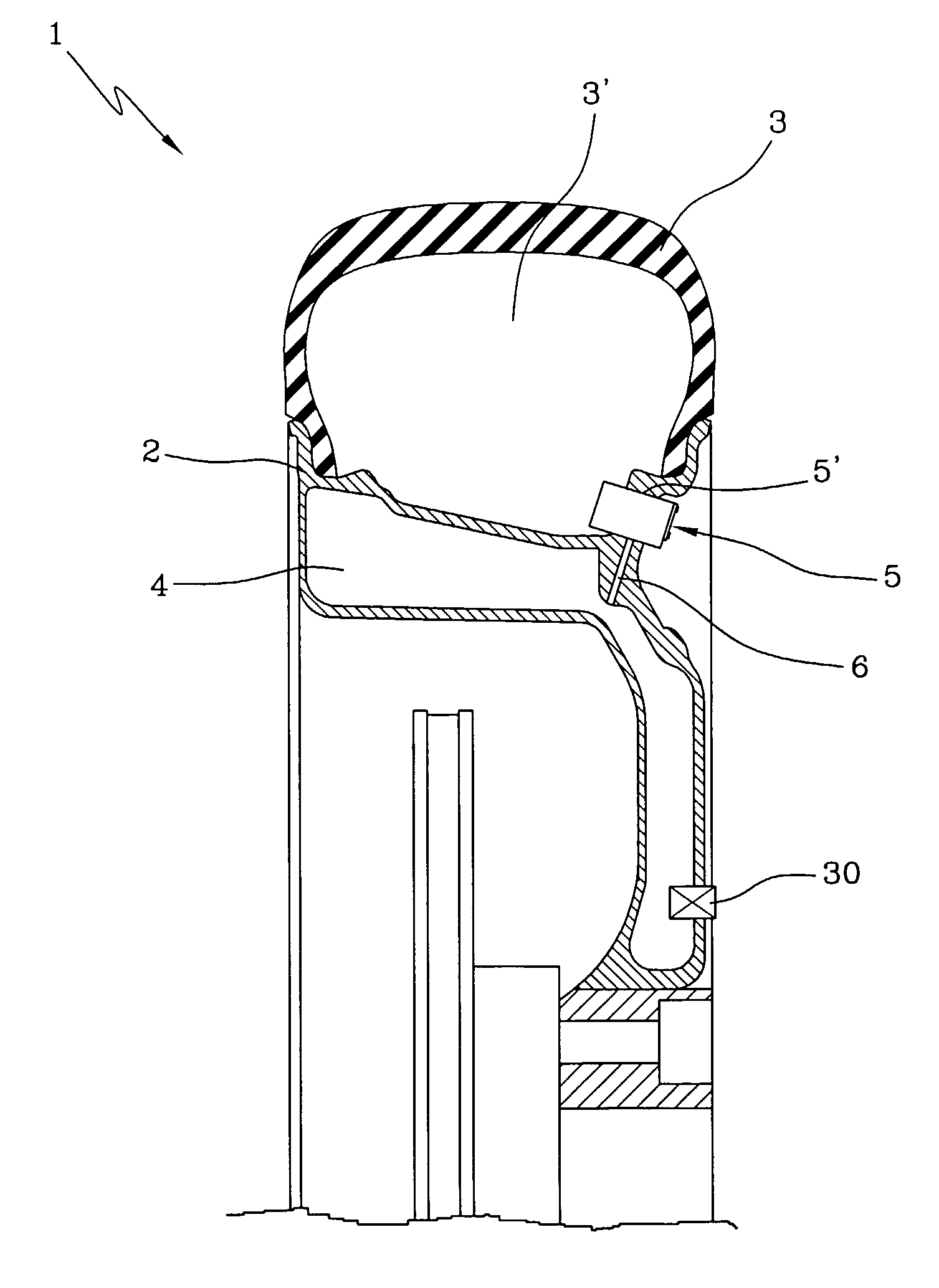
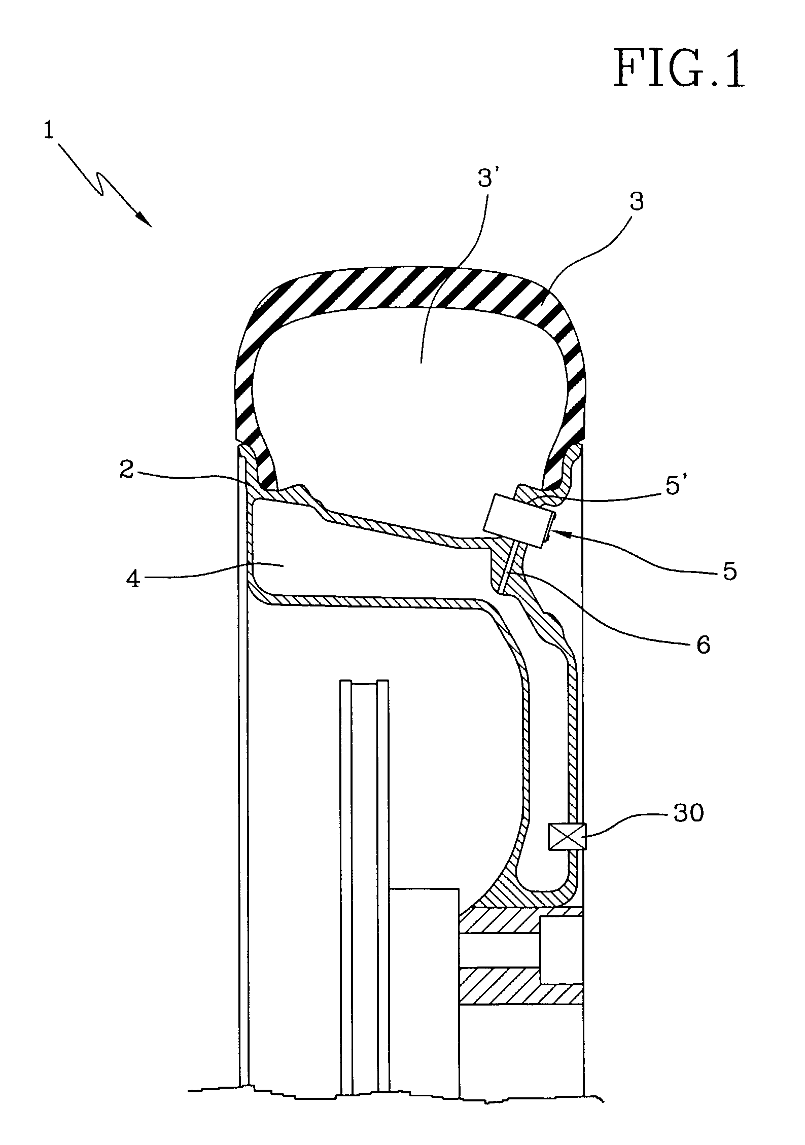
[0053]As shown in FIG. 1, the wheel 1 for two-wheeled or four-wheeled vehicles in accordance with the invention comprises a rim 2 on which a tyre 3 having an inner volume 3′ is mounted. Associated with rim 2 and preferably integrated thereinto is a tank 4 suitable to contain a fluid under pressure, said fluid being air or a substantially inert gas such as nitrogen, for example.

[0054]According to a preferred embodiment, the ratio between the operating pressure of tyre 3 and a first pressure existing in said tank 4 when fully loaded varies between about 0.1 and about 0.6, preferably between about 0.2 and about 0.4.

[0055]In accordance with a further preferred embodiment, the ratio between the volume of said tank 4 and said inner volume 3′ of the tyre is included between about 0.1 and about 0.4, preferably between about 0.12 and about 0.25.

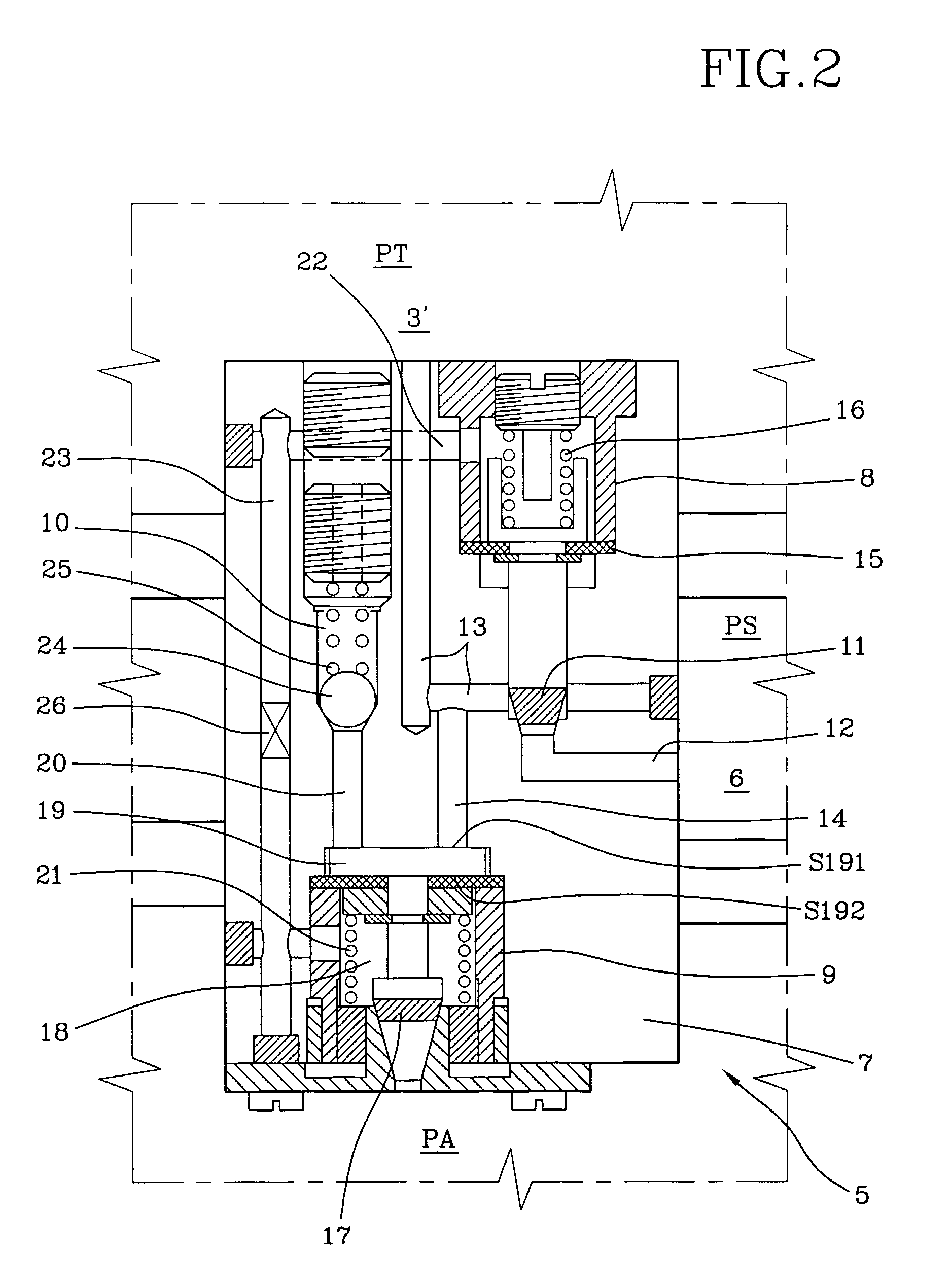
[0056]The rim 2 preferably houses a valve assembly 5 of the mechanical type in a seat 5′ formed at a radially external position, which valve assembly...


PUM

PropertyMeasurementUnit
pressureaaaaaaaaaa
temperatureaaaaaaaaaa

Abstract

A wheel having a controlled pressure includes a rim associated with a tank adapted to be filled with a fluid to a first pressure; a tire mounted on the rim and having an inner volume inflated to an operating pressure at a reference temperature, the operating pressure being lower than the first pressure; and at least one valve assembly adapted to establish a communication between the tank, the inner volume of the tire and the external environment. The valve assembly includes a command valve, an exhaust valve and a compensation valve operatively associated with each other. The command valve controls communication between the tank and the inner volume of the tire. The exhaust valve is connected to the external environment, to the inner volume, to the command valve and to the compensation valve. The compensation valve is connected to the exhaust valve and the command valve. The command valve includes an inner chamber connected with the exhaust valve and the compensation valve in such a manner that the command valve is operated by the exhaust valve and the compensation valve through a pressure variation of the inner chamber in response to a variation of the inner pressure of the tire.

Description

CROSS REFERENCE TO RELATED APPLICATION[0001]This application is a national phase application based on PCT / IB2004 / 001236, filed Apr. 23, 2004, the content of which is incorporated herein by reference.BACKGROUND OF THE INVENTION[0002]1. Field of the Invention[0003]The present invention relates to a wheel having a controlled pressure.[0004]2. Description of the Related Art[0005]A wheel for two-wheeled or four-wheeled vehicles generally comprises a rim coupled with a pneumatic tyre that is inflated to a predetermined operating pressure.[0006]Said tyre generally comprises a carcass structure having at least one carcass ply and at least one annular reinforcing structure associated with the carcass ply, a tread band of an elastomer material at a radially external position to the carcass structure, a belt structure interposed between the carcass structure and the tread band and a pair of sidewalls located at axially opposite positions on the carcass structure.[0007]In tubeless tyres the tyr...

Claims


Application Information

Patent Timeline
Patent Type & Authority Patents(United States)
IPC IPC(8): B60C23/00B60C23/16
CPCB60C23/004Y10T152/10522Y10T152/10729B60C23/12B60C23/04
Inventor CARETTA, RENATOPIANTANIDA, PIER GIUSEPPESANGIOVANNI, STEFANOMARCHINI, MAURIZIOSGALARI, GIORGIA
Owner PIRELLI TYRE SPA
Why Eureka
Try Eureka