
Automatic focusing apparatus and optical device

a technology of automatic focusing and optical devices, which is applied in the direction of focusing aids, instruments, television systems, etc., can solve the problems of image focusing performance degradation of liquid crystal lenses, and it takes an appreciable amount of time to detect a focusing point, so as to reduce the voltage applied, and improve the focusing performance

Inactive Publication Date: 2011-03-22
CITIZEN WATCH CO LTD
View PDF28 Cites 11 Cited by
  • Summary
  • Abstract
  • Description
  • Claims
  • Application Information

AI Technical Summary

Benefits of technology

The present invention provides an automatic focusing apparatus and an optical device that can detect a focusing point quickly and accurately. The apparatus includes a liquid crystal lens that takes a long time to detect a focusing point because of its slow response speed. However, the invention provides a solution by applying a high voltage to the liquid crystal lens to speed up the detection process, but this also degrades the image quality. The invention solves this problem by reducing the voltage applied to the liquid crystal lens when adjusting the focusing point, and identifying the focus signals based on the image signal. The invention also includes a temperature detection unit to adjust the voltage based on the detected temperature. The technical effects of the invention are faster and more accurate automatic focusing and improved image quality.

Problems solved by technology

However, the liquid crystal lens has the problem that it takes an appreciable amount of time to detect a focusing point, because the response speed of the liquid crystal is slow.
However, in the presence of a high voltage, the image focusing performance of the liquid crystal lens degrades.

Method used


Image

  • Automatic focusing apparatus and optical device
  • Automatic focusing apparatus and optical device
  • Automatic focusing apparatus and optical device

Examples


Embodiment Construction

[0049]The preferred embodiments of automatic focusing apparatus according to the present invention will be described in detail below with reference to the drawings. However, it should be noted that the present invention is not limited by the description given herein, but covers the inventions described in the appended claims and their equivalents.

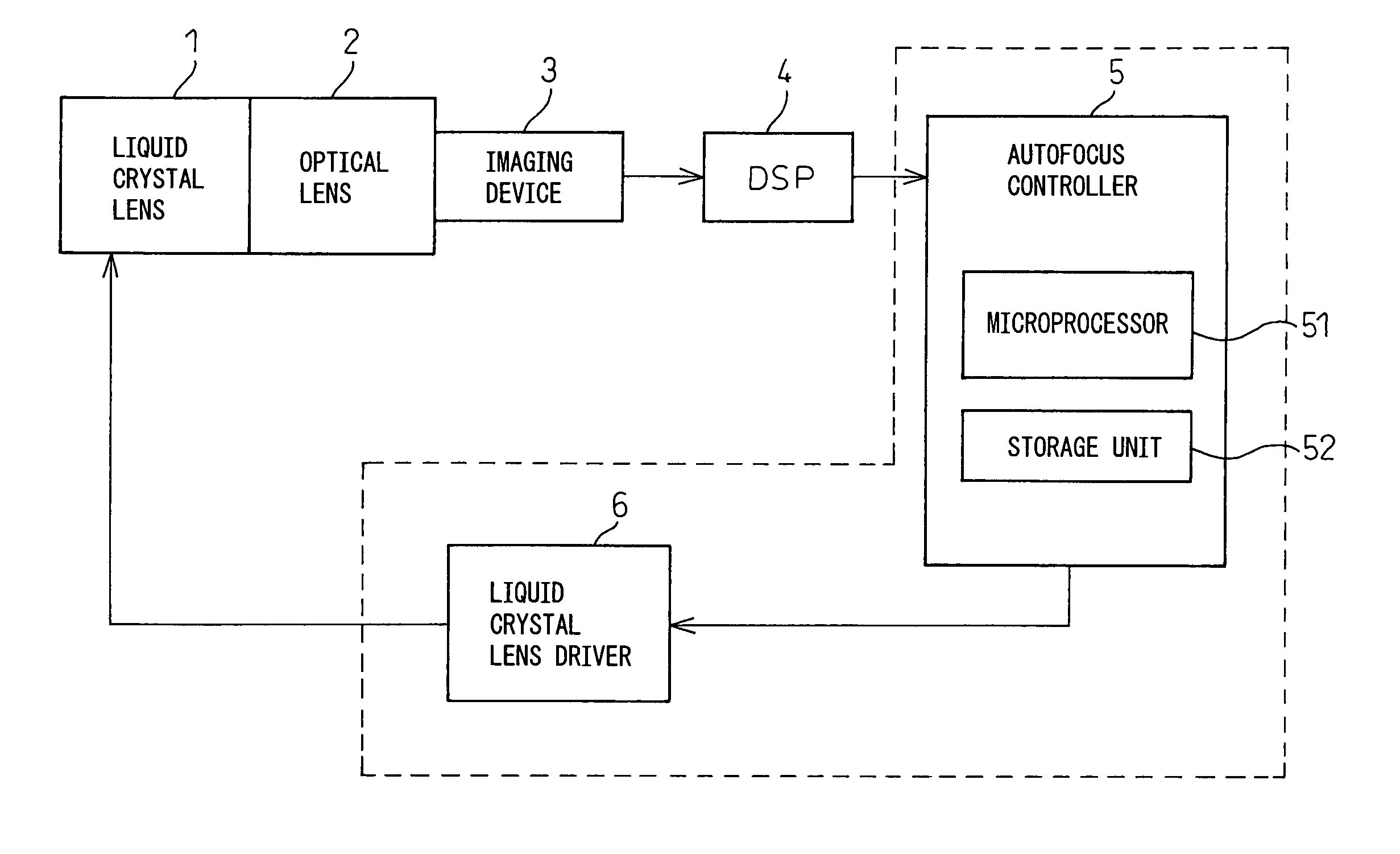
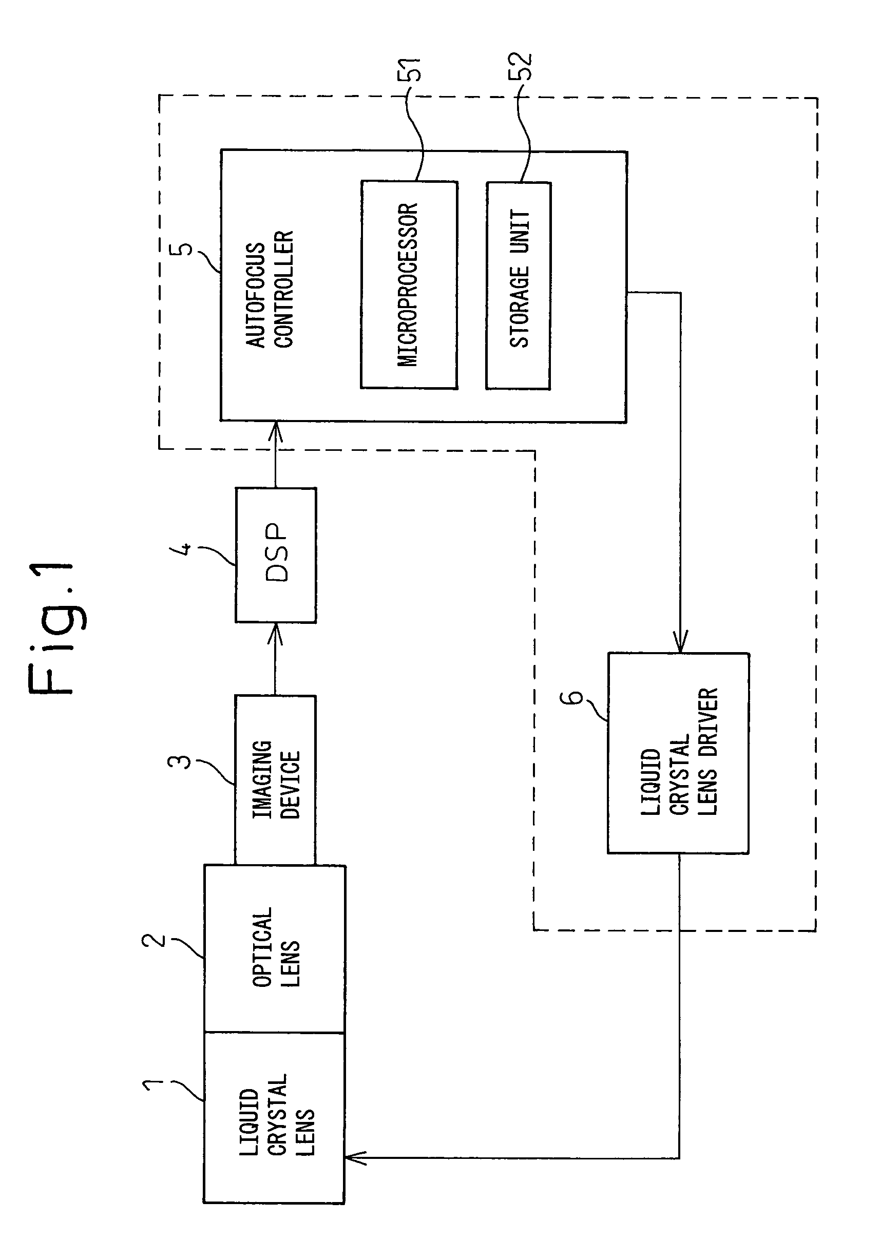
[0050]FIG. 1 is a block diagram showing the basic configuration of an automatic focusing apparatus according to the present invention.

[0051]As shown in FIG. 1, the automatic focusing apparatus of the present invention comprises a liquid crystal lens 1, an optical lens 2, an imaging device 3, a DSP (Digital Signal Processor) 4, an autofocus controller 5, and a liquid crystal lens driver 6. Liquid crystal lens 1 is constructed by combining a liquid crystal lens for P waves with a liquid crystal lens for S waves. Optical lens 2 comprises a diaphragm, a group of pan focus lens elements, and an infrared cutoff filter. Imaging device 3 comprises ...


PUM


Abstract

The present invention is directed to the provision of an automatic focusing apparatus that can detect a focusing point at a sufficiently high speed for practical use and can achieve a lens condition having good focusing performance. The automatic focusing apparatus of the present invention includes a liquid crystal lens which forms a refractive index profile, an optical-to-electrical conversion unit which converts an optical image focused through the liquid crystal lens into an electrical signal and outputs the electrical signal as an image signal, a focus signal extracting unit which causes the refractive index profile to change by applying a first range of voltage to the liquid crystal lens, and extracts a plurality of focus signals based on the image signal, a focusing point identifying unit which identifies a focus signal corresponding to a focusing point from among the plurality of extracted focus signals, and a focusing point adjusting unit which adjusts the focusing point by applying to the liquid crystal lens a second voltage that is capable of generating the refractive index profile corresponding to the focus signal identified by the focusing point identifying unit and that is smaller than the first range of voltage applied to the liquid crystal lens in order to obtain the focus signal identified by the focusing point identifying unit.

Description

FIELD OF THE INVENTION[0001]The present invention relates to an automatic focusing apparatus and an optical device. More specifically, the invention relates to an automatic focusing apparatus that uses a liquid crystal lens for adjustment of focal length, extracts a plurality of focus signals corresponding to the degree of focusing from an image signal obtained from an optical image focused through the liquid crystal lens, and detects a focusing point by detecting the peak value of the plurality of focus signals, and the invention also relates to an optical device for use in the same.BACKGROUND OF THE INVENTION[0002]A method that achieves focusing by moving a lens or lenses is widely employed to implement a focusing system for varying the focal length or focus position of an optical system. However, this method requires the use of a lens driving mechanism, and therefore has the drawbacks that the focusing system is complex, and that a relatively large amount of power is required to ...

Claims


Application Information

Patent Timeline
Patent Type & Authority Patents(United States)
IPC IPC(8): H04N5/232
CPCG02B7/38H04N5/23212G03B13/36H04N23/673
Inventor KAGEYAMA, YASUHIRO
Owner CITIZEN WATCH CO LTD
Learn More