Electronic device

a technology of electronic devices and heat dissipation mechanisms, which is applied in the direction of electrical apparatus casings/cabinets/drawers, cooling/ventilation/heating modifications, instruments, etc., can solve the problems of affecting the heat dissipation efficiency, so as to achieve easy and quick removal and good heat dissipation

Inactive Publication Date: 2011-03-22
WISTRON CORP
View PDF27 Cites 15 Cited by
  • Summary
  • Abstract
  • Description
  • Claims
  • Application Information

AI Technical Summary

Benefits of technology

[0009]Therefore, an object of the present invention is to provide an electronic device having a heat-dissipating fan that is convenient to assemble and disassemble and that is easy to clean so as to maintain a good heat-dissipating effect.
[0024]In the embodiments of the electronic device according to this invention, by providing the heat-dissipating fins and the heat-dissipating fan separately, and by forming the opening in one of the first base wall and the second base wall, the heat-dissipating fan can be easily and quickly removed from the housing through a lower side or a lateral side of the housing for cleaning of a casing and a fan body of the heat-dissipating fan, and the heat-dissipating fins. Thus, air passages between the heat-dissipating fan and the heat-dissipating fins can be kept clear to ensure smooth flow of air therethrough for maintaining good heat-dissipation.

Problems solved by technology

After a period of use of the notebook computer 1, the problem of dust accumulation will aggravate, resulting in blocking of air passages in the heat-dissipating module 13 and obstructed airflow.
This in turn results in deterioration of the heat-dissipating efficiency.
As a consequence, the notebook computer 1 may crash due to overheating of the heat-generating element 12.
If subsequent handling is not done properly, the heat generated by the heat-generating element 12 cannot be effectively transmitted to the heat-dissipating sheet 135 through the heat-dissipating paste after the heat-dissipating module 13 is re-assembled to the body 110 of the housing 11, thereby resulting in poor heat dissipation.
Moreover, since it is necessary for the heat-dissipating sheet 135 to exert a certain pressure on the heat-generating element 12, if the casing 130 is secured to the body 110 with an insufficient or uneven force, contact between the heat-dissipating sheet 135 and the heat-generating element 12 will be defective, which will in turn result in poor heat dissipation.

Method used


Image

  • Electronic device
  • Electronic device
  • Electronic device

Examples


Embodiment Construction

[0039]Before the present invention is described in greater detail, it should be noted that like elements are denoted by the same reference numerals throughout the disclosure.

[0040]In addition, directional terms, such as upper, lower, top, bottom, left, right, front, and rear, are used herein with reference to the orientation of the accompanying drawings. Thus, such directional terms are for purposes of illustration and are in no way limiting.

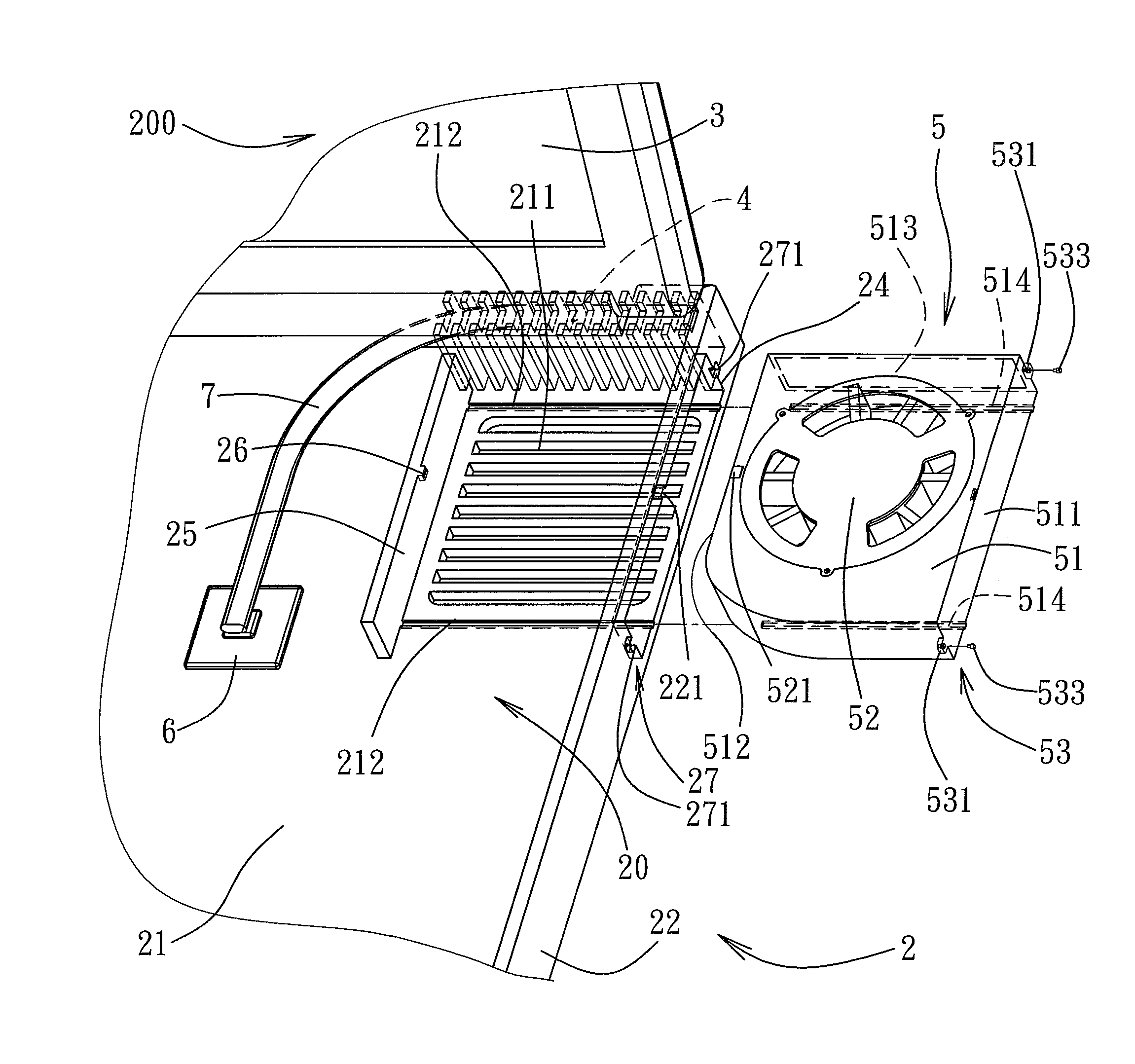
[0041]Referring to FIG. 5, the first preferred embodiment of an electronic device 200 according to the present invention is exemplified to be a notebook computer. The electronic device 200 includes a housing 2, a keyboard 8, a display screen 3 connected pivotally to the housing 2, a plurality of heat-dissipating fins 4, a heat-dissipating fan 5, a heat-generating element 6, and a heat pipe 7. Although the electronic device 200 is exemplified as a notebook computer in this embodiment, the electronic device 200 may be a game console or any other c...


PUM


Abstract

An electronic device includes a housing, a plurality of heat-dissipating fins, and a heat-dissipating fan. The housing defines a receiving space, and an opening communicating the receiving space with the outside environment. The housing includes a power socket disposed in the receiving space. The heat-dissipating fins are disposed in the receiving space. The heat-dissipating fan includes a power plug portion corresponding to the power socket. The heat-dissipating fan is mountable in the receiving space through the opening so as to provide air flow across the heat-dissipating fins. The power plug portion is inserted into the power socket upon insertion of the heat-dissipating fan into the receiving space. The heat-dissipating fan is removable from the housing through the opening for cleaning of the heat-dissipating fan and the heat-dissipating fins.

Description

CROSS-REFERENCE TO RELATED APPLICATION[0001]This application claims priority of Taiwanese Application No. 096146536, filed on Dec. 6, 2007.BACKGROUND OF THE INVENTION[0002]1. Field of the Invention[0003]The invention relates to a heat-dissipating mechanism for an electronic device, more particularly to a heat-dissipating mechanism that is convenient to disassemble and assemble and that is easy to clean.[0004]2. Description of the Related Art[0005]As shown in FIGS. 1, 2 and 3, a heat-generating element 12 (such as a central processing unit or a graphics processing chip) within a housing 11 of a conventional notebook computer 1 will generate a large amount of heat during operation. A heat-dissipating module 13 is therefore required to dissipate the heat generated by the heat-generating element 12 to the outside of the housing 11, so as to prevent crashing of the notebook computer 1 due to the heat. However, since there are dust or suspended particles in the air, when air passes throug...

Claims


Application Information

Patent Timeline
Patent Type & Authority Patents(United States)
IPC IPC(8): H05K7/20
CPCG06F1/203
Inventor CHAO, CHIEN-CHIHCHENG, KUEI-YUNG
Owner WISTRON CORP
Why Eureka
Try Eureka