
Embedded type system positioning spinning method

a technology of embedded type and positioning spinnery, which is applied in the direction of yarn, continuous wounding machine, textiles and paper, etc., can solve the problems of not meeting the wrapping effect is not very good, and the above-mentioned spinning process can not meet the demand for various types of yarn, so as to prevent the end from breaking, the range of textile material is enlarged, and the hairiness and strength of the yarn are better

Inactive Publication Date: 2011-03-29
SHANDONG RUYI SCI & TECH GRP +2
View PDF6 Cites 16 Cited by
  • Summary
  • Abstract
  • Description
  • Claims
  • Application Information

AI Technical Summary

Benefits of technology

[0005]An object of the present invention is to provide an embedded type system positioning spinning method, which can produce the multi-component multi-structure yarn on one ring spinning frame, so as to meet the demand for new textile materials and special structures.
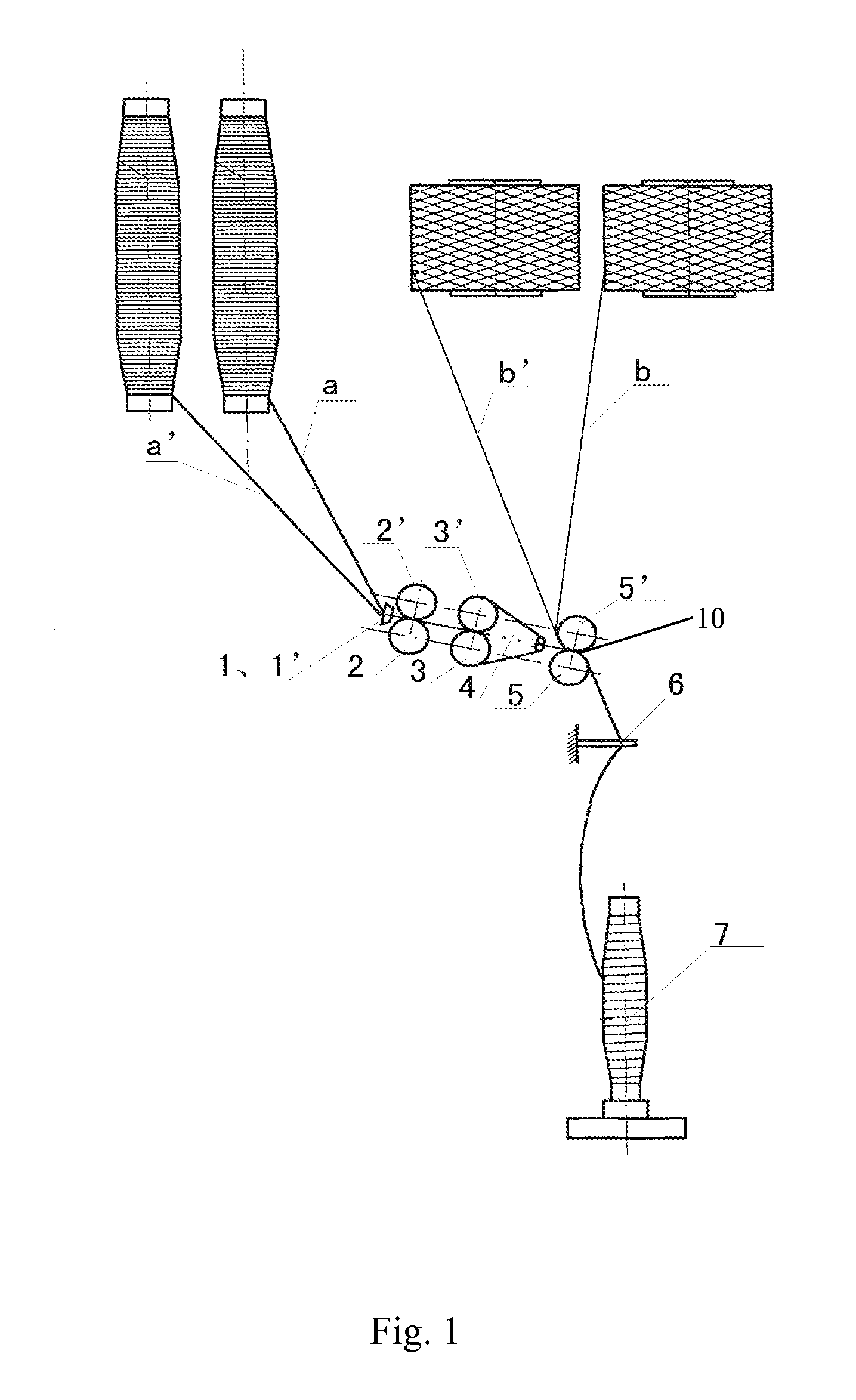
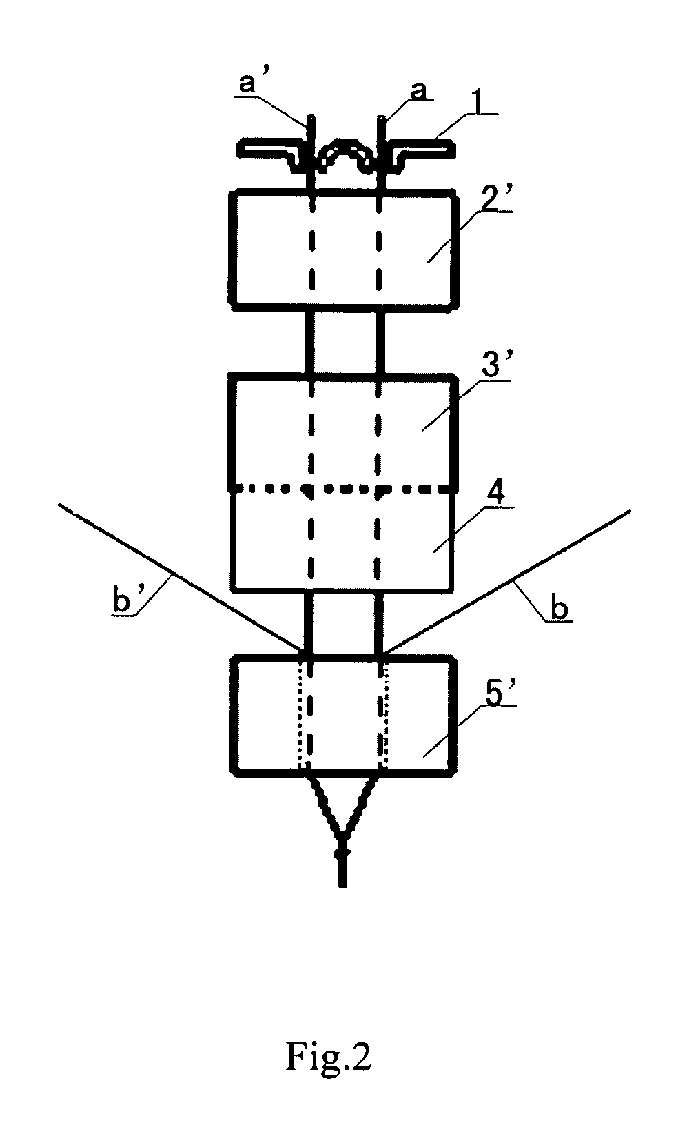
[0008]In the above process, by changing the relative position between the fed two short-staple rovings and two filaments, the multi-component yarn with core structure, wrapped structure, or strand-like structure can be produced on one ring spinning frame. The structure of the yarn can be precisely determined. The structure of the yarn is more compact, and the hairiness and strength of the yarn are better. In the present invention, the two filaments can strengthen the output two rovings in the twisting triangle area, so as to prevent the breaking ends. Special fiber yarns, such as hemp and apocynum, can be produced on a traditional spinning device, so that the range of textile material is enlarged. At the same time, the alteration on the original device is simple and the altered device is convenient to use.

Problems solved by technology

However, the above-mentioned spinning processes still can not meet the demand for various types of yarns.
For example, though Sirofil spinning can produce the core structure yarn with a filament and a short-staple roving, the wrapping effect is not very good, i.e. the yarn in center easily comes out; Siro spinning can double and twist two rovings, but there will be a lot of broken ends when producing the high count yarn, because the number of the fibers of each roving strand in the twisting triangle area is very small.

Method used


Image

  • Embedded type system positioning spinning method
  • Embedded type system positioning spinning method
  • Embedded type system positioning spinning method

Examples


example 1

Producing the Silk Style Yarn by the Cotton Ring Spinning Frame

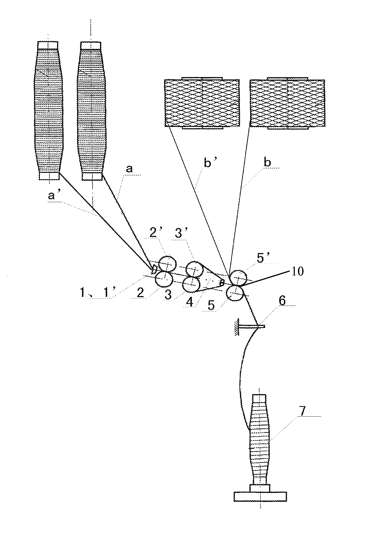
[0021]Two cotton rovings a and a′ from the roving bobbin enter the draft mechanism to be drafted through two guide funnels 1 and 1′ in parallel, respectively; two silks b and b′ are fed from the back of the front roller 5 via a guide wire or a guide wheel. The silks b and b′ must be parallel with the cotton rovings a and a′ respectively. The silks b and b′ are at the outer side of the cotton rovings a and a′. The drafted two cotton rovings a and a′ and two silks b and b′ are output from the front jaw 10 and enter the twisting triangle area to be twisted, and then are wound onto a yarn bobbin 7 via a guide wire 6. The yarn produced in this method has silk surface and cotton roving core, so that the fabric made of this kind of yarn has silk style, and cost is extremely lowered.

example 2

Producing the Wool Core Spun Yarn

[0022]Two wool rovings a and a′ from the roving bobbin enter into the draft mechanism to be drafted through two guide funnels 1 and 1′ in parallel, respectively; two polyester filaments b and b′ are fed from the back of the front roller 5 via a guide wire or a guide wheel. The polyester filaments b and b′ must be parallel with the wool rovings a and a′ respectively. The polyester filaments b and b′ are at the inner side of the wool rovings a and a′. The drafted two wool rovings a and a′ and two polyester filaments b and b′ are output from the front jaw 10 and enter into the twisting triangle area to be twisted, and then are wound onto a yarn bobbin 7 via a guide wire 6. The yarn produced in this method has wool surface and polyester filament core, so that the yarn has wool style, and cost is extremely lowered.

example 3

Producing the Ramie High Count Yarn

[0023]Two ramie rovings a and a′ from the roving bobbin enter the draft mechanism to be drafted through two guide funnels 1 and 1′ in parallel, respectively; two fine denier polyester filaments of 50-200 denier b and b′ are fed from the back of the front roller 5 via a guide wire or a guide wheel. The polyester filaments b and b′ must be parallel with the ramie rovings a and a′ respectively, wherein the polyester filament b and the roving a overlap and the polyester filament b′ and the roving a′ overlap. The drafted two ramie rovings a and a′ and two polyester filaments of b and b′ are output from the front jaw 10 and enter the twisting triangle area to be twisted, and then are wound onto a yarn bobbin 7 via a guide wire 6.

[0024]The ramie is difficult to be used to produce high count yarn, because of crude fiber, high stiffness and poor cohesive force. Though high count yarn with over 80 deniers can be produced by adopting Sirofil spinning, the pro...


PUM

PropertyMeasurementUnit
water solubleaaaaaaaaaa
structuresaaaaaaaaaa
densityaaaaaaaaaa

Abstract

On each draft element of a ring spinning frame, two pieces of short-staple roving from the roving bobbin enter into the draft mechanism to be drafted though a guide funnel in parallel, two pieces of filament are fed from the back of the front roller, and combine with two pieces of roving at front jaw respectively. The drafted two pieces of roving and filament are output from the front jaw and enter into the twisting triangle area to be twisted, and then are wound onto a yarn bobbin to produce yarn. Based on the relative position of the two pieces of roving and two pieces of filament, different yarns can be produced. Furthermore, multi-component yarn, such as core structure, wrapped structure, strand-like structure, can be produced on a ring spinning frame. The structure of yarn can be precisely determined. Special fiber yarn can be produced on traditional spinning frame.

Description

BACKGROUND OF THE PRESENT INVENTION[0001]1. Field of Invention[0002]The present invention relates to a spinning process, and more particularly to a spinning method that can produce yarns of various structures using a ring spinning frame.[0003]2. Description of Related Arts[0004]With the development of the textile material and increasing demand for style and design of the costume fabric, the demand for spinning process is higher and higher, such as super high count yarn and multi-component composite yarn. More researches focus on the spinning process, and various spinning processes have been developed, such as Sirofil spinning, Siro spinning, compact spinning, and cable spinning. These new spinning processes greatly improve the yarn quality. For example, Sirofil spinning can produce the core structure yarn with a filament and a short-staple roving; Siro spinning can double and twist two rovings, which can improve the spinning quality and the fineness of the yarn; cable spinning divid...

Claims


Application Information

Patent Timeline
Patent Type & Authority Patents(United States)
IPC IPC(8): D02G3/36
CPCD01H1/006D02G3/281D02G3/367
Inventor QIU, YAFUXU, WEILINQIU, DONGDING, CAILINGCUI, WEIGANGWANG, WENGESHEN, XIAOLINYANG, AIGUOLI, BAOCANGWANG, JIANPINGQIN, GUANG
Owner SHANDONG RUYI SCI & TECH GRP
Learn More