
Burner for combustion chamber and combustion method

a combustion chamber and burner technology, applied in the direction of machines/engines, mechanical equipment, lighting and heating apparatus, etc., can solve the problems of difficult poor combustion stability and combustion efficiency, and difficulty in ignition at low temperatures, so as to shorten the overall length of the burner and improve combustion efficiency , the effect of shortening the flame length

Active Publication Date: 2011-03-29
IHI CORP
View PDF38 Cites 10 Cited by
  • Summary
  • Abstract
  • Description
  • Claims
  • Application Information

AI Technical Summary

Benefits of technology

[0007]The present invention was achieved in view of the above circumstances, and has as its object to provide a burner for combustion chamber and a combustion method that can shorten the flame length in the central axial direction of the burner for combustion chamber by improving the combustion efficiency even during low loading and shorten the overall length of the burner for combustion chamber in the central axial direction.
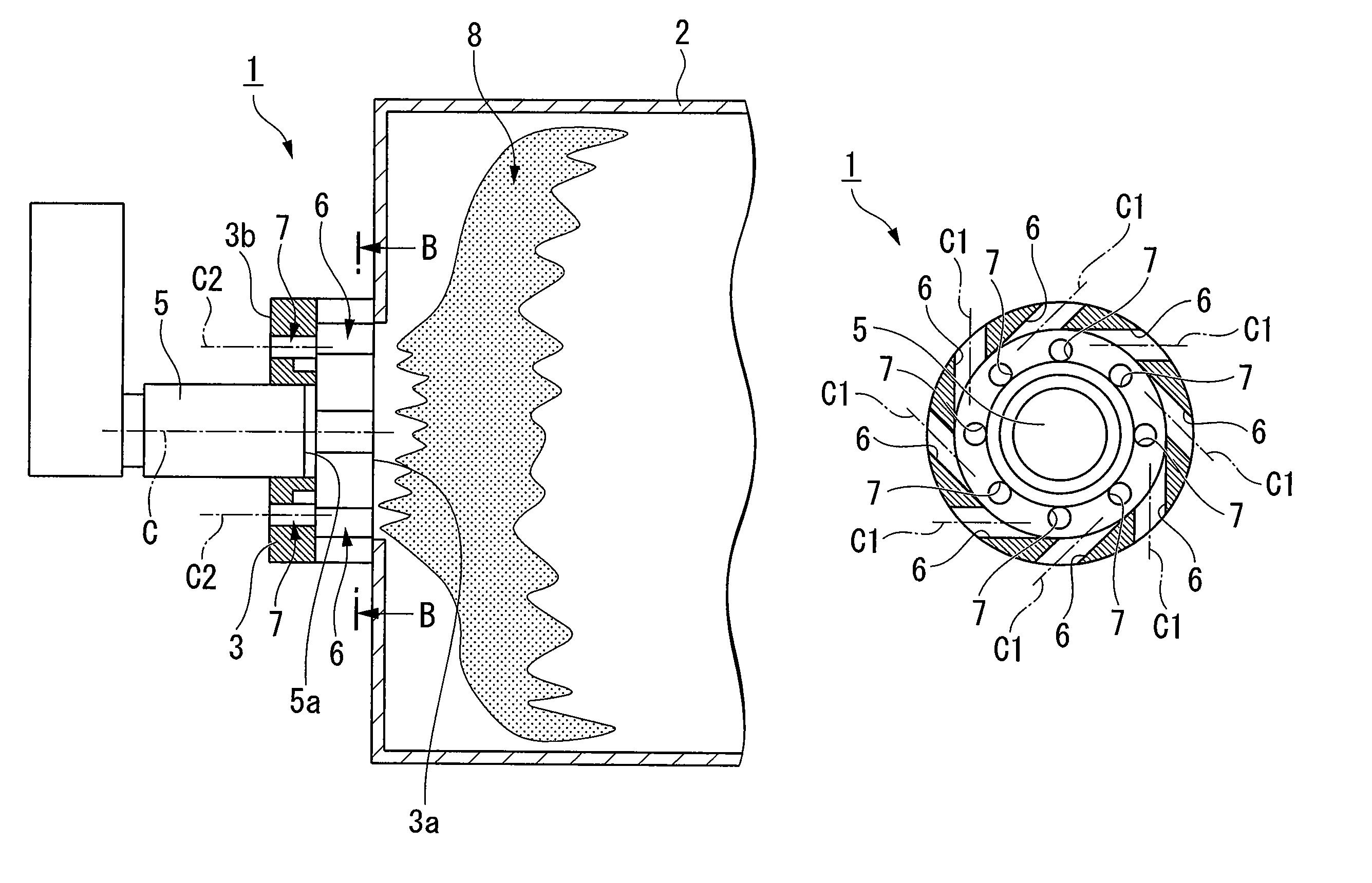
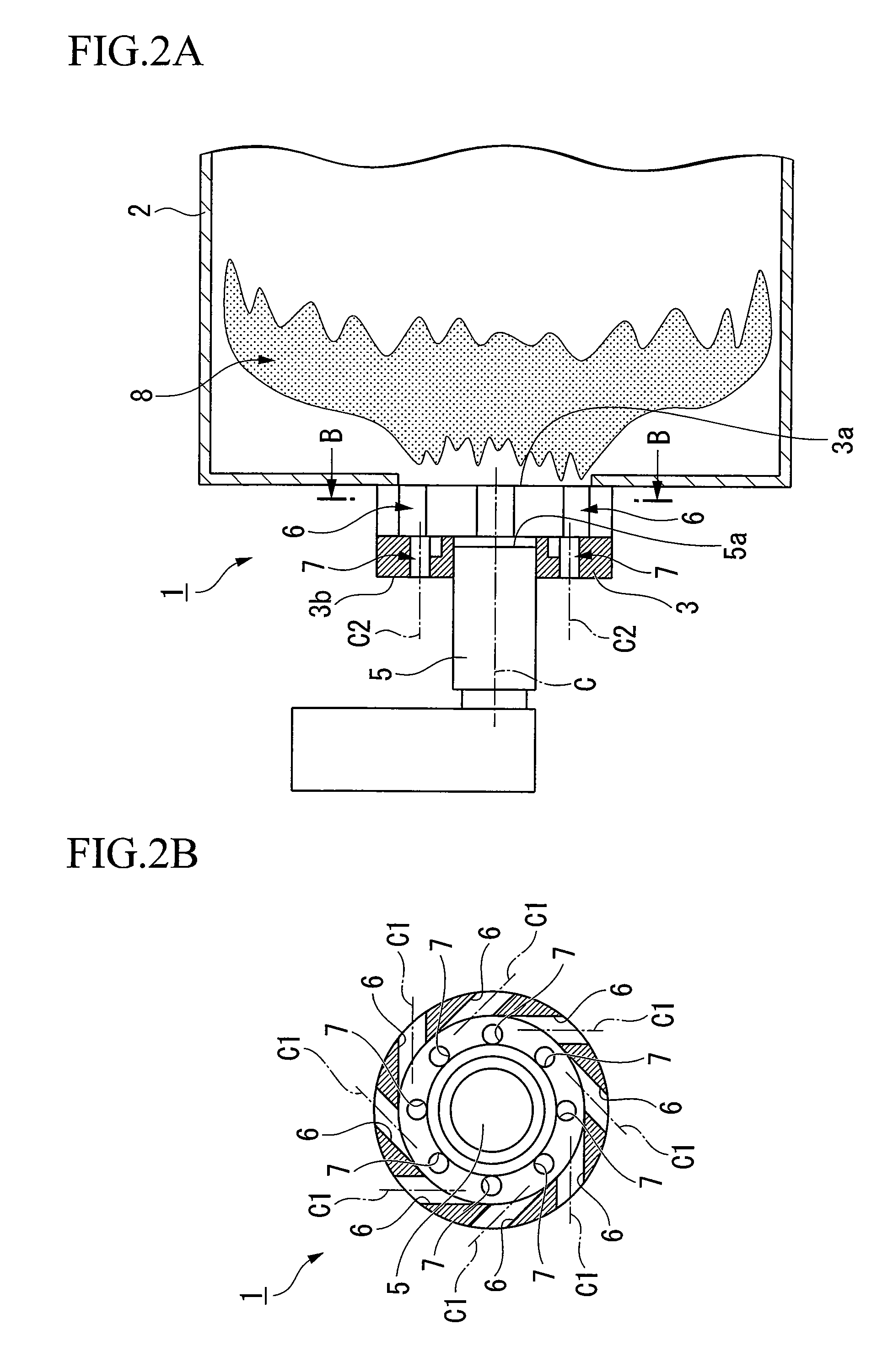
[0009]This invention can form a strong swirling flow of an air-fuel mixture consisting of fuel that is sprayed from the fuel spraying portion and the oxidizing agent that is introduced to the mixing portion from the first blowing ports. Also, by introducing the oxidizing agent into the mixing portion from the second blowing ports, it can be made to collide with the strong swirling flow. Thereby, a vortex breakdown can be caused by partially destroying the strong swirling flow. Accordingly, a stronger turbulence state can be formed than in the case of a strong swirling flow alone, thereby accelerating the mixture of the fuel and the oxidizing agent. At this juncture, the flammable zone in the combustion portion at the one end side of the mixing portion can be greatly expanded in the diameter direction by the moderate swirling that remains and the large turbulence. As a result, it is possible to shorten the distance between the combustion portion and the mixing portion.
[0013]In this invention, the strong swirling flow due to the oxidizing agent that is introduced from the first blowing ports collides with the distal end of the fuel spraying portion. Thereby, a strong shear flow can be formed around the fuel spraying portion. Accordingly, it is possible to produce greater turbulence, which can accelerate rapid mixing.
[0015]The present invention can shorten the flame length in the central axial direction of the burner for combustion chamber by improving the combustion efficiency even during low loading and can shorten the overall length of the burner for combustion chamber in the central axial direction.

Problems solved by technology

In particular, in the case of a combustion chamber having a wide load range such as in an aircraft engine, when such a separation state occurs during a low load, the flame is formed only at the rigid vortex area, and the mixing of fuel and air therefore becomes insufficient, leading to a worsening of combustion stability and combustion efficiency.
In such a case, ignition performance drops, and ignition at low temperatures becomes difficult.
Thereby, a vortex breakdown can be caused by partially destroying the strong swirling flow.

Method used


Image

  • Burner for combustion chamber and combustion method
  • Burner for combustion chamber and combustion method
  • Burner for combustion chamber and combustion method

Examples


first embodiment

[0027]the present invention will be described below with reference to FIGS. 1A to 3.

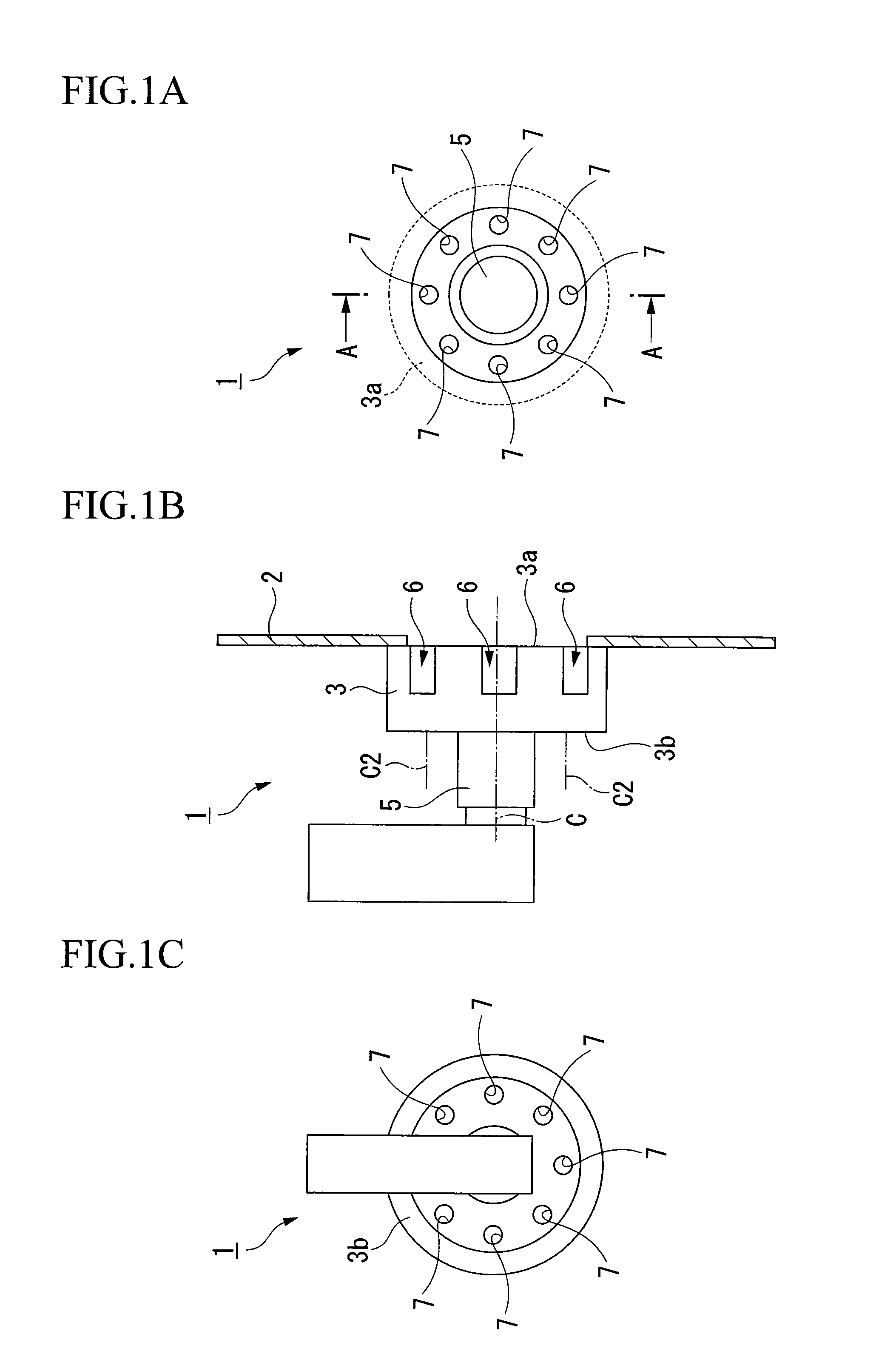
[0028]As shown in FIGS. 1A, 1B, and 1C, a burner 1 for combustion chamber according to the first embodiment of the present invention is provided with the following: a cylindrical mixing portion 3 that mixes air for combustion (oxidizing agent) and fuel in the interior thereof, with one end 3a opening to a combustion portion 2; a spray nozzle (fuel spraying portion) 5 that sprays fuel in the mixing portion 3, being disposed on another end 3b of the mixing portion 3; a plurality of first blowing ports 6 that introduce the air for combustion to the mixing portion 3 to form a swirling flow with the fuel, being disposed to open to the inner wall of the mixing portion 3; and a plurality of second blowing ports 7 that additionally introduce the air for combustion to the mixing portion 3, opening in a direction different from the flow of the swirling flow and being disposed further to the other end 3b side o...

second embodiment

[0039]Next, a second embodiment shall be described with reference to FIGS. 4A and 4B.

[0040]In this embodiment, constituent elements identical to those in the first embodiment are identified with the same reference numbers, with explanations thereof omitted.

[0041]As shown in FIG. 4A, the point of difference of the second embodiment and the first embodiment is that a distal end 5a of the spray nozzle 5 in a burner 10 for combustion chamber according to the present embodiment is disposed projecting from another end 11b to the side of a distal end 11a of a mixing portion 11 along the central axis C until the disposed position of the first blowing ports 6.

[0042]The combustion method of this burner 10 for combustion chamber and the action and effect thereof shall be described.

[0043]First, air for combustion is introduced from the first blowing ports 6 and the second blowing ports 7 into the mixing portion 11, and fuel in a spray form is injected into the mixing portion 11 from the spray n...

third embodiment

[0048]Next, a third embodiment will be described with reference to FIGS. 5A and 5B.

[0049]In this embodiment, constituent elements identical to those in the other embodiments described above are identified with the same reference numbers, with explanations thereof omitted.

[0050]As shown in FIG. 5B, the point of difference of the third embodiment and the second embodiment is that a second blowing port 16 of a burner 15 for combustion chamber according to the present embodiment is formed as a circular slit.

[0051]The width of this second blowing port 16 is approximately the same as the inner diameter of the second blowing ports 7 according to the first and second embodiments, and is provided in a manner that makes the second blowing ports 7 continuous in the circumferential direction.

[0052]The outside diameter of a spray nozzle 17 is formed to be of a smaller diameter than the spray nozzle 5 according to the first and second embodiments, and the outside diameter of a mixing portion 18 i...


PUM


Abstract

A burner 1 for combustion chamber is provided with a cylindrical mixing portion 3 that mixes air for combustion (oxidizing agent) and fuel in the interior thereof and has one end 3a that opens to a combustion portion 2; a spray nozzle (fuel spraying portion) 5 that sprays fuel in the mixing portion 3, being disposed on another end 3b of the mixing portion 3; first blowing ports 6 that introduce the air for combustion to the mixing portion 3 to form a swirling flow with the fuel, being disposed to open to the inner wall of the mixing portion 3; and second blowing ports 7 that additionally introduce the air for combustion to the mixing portion 3, opening in a direction different from the first blowing ports 6 and being disposed further to the other end 3b side of the mixing portion 3 than the swirling flow. The burner for combustion chamber and combustion method of the present invention can shorten the flame length in the central axial direction by improving the combustion efficiency even during low loading and shorten the overall length of the burner for combustion chamber in the central axial direction.

Description

BACKGROUND OF THE INVENTION[0001]1. Field of the Invention[0002]The present invention relates to a burner for a combustion chamber that performs combustion by rapidly mixing fuel and an oxidizing agent such as air, and to a combustion method thereof.[0003]Priority is claimed on Japanese Patent Application No. 2006-080881, filed Mar. 23, 2006, the content of which is incorporated herein by reference.[0004]2. Description of Related Art[0005]In recent years, there have been growing demands to reduce the concentration of nitrogen oxide (NOx) in the combustion exhaust of gas turbines and the like for the sake of environmental protection. In order to satisfactorily mix fuel and an oxidizing agent such as air, there has been proposed a burner having a cylindrical mixing portion in which fuel in a spray form and air for combustion, which is introduced from tangential to the cross section of the mixing portion, are introduced to generate a turbulent state by forming a strong swirling flow (r...

Claims


Application Information

Patent Timeline
Patent Type & Authority Patents(United States)
IPC IPC(8): F02C1/00F02G3/00
CPCF23C7/002F23R3/12F23R3/286F23D2900/14021
Inventor HIROMITSU, NAGAYOSHIHOSOI, JUNFUJII, ATSUSHISAITOU, TSUKASARIECHELMANN, DIRKSATO, JUNICHI
Owner IHI CORP
Learn More