High frequency electrical connector

a high-frequency electrical connector and high-frequency technology, applied in the direction of securing/insulating coupling contact members, coupling device connections, printed circuits, etc., can solve the problems of undesired signal and crosstalk, signal weakening, signal weakening, etc., to improve high-frequency performance

Inactive Publication Date: 2011-03-29
HON HAI PRECISION IND CO LTD
View PDF4 Cites 36 Cited by
  • Summary
  • Abstract
  • Description
  • Claims
  • Application Information

AI Technical Summary

Benefits of technology

[0006]An object of the invention is to provide an electrical connector with new contacts to improve high frequency performance thereof.
[0007]In order to achieve the object set forth, an electrical connector assembly has an elongated insulative housing and a plurality of signal contacts secured in corresponding passageways defined in the housing. Each signal contact has a retention portion retained in the passageway, a contact portion extending from the retention portion and a soldering portion extending from the retention portion. The contact portion defines a first face exposing an exterior of the passageways and a second face opposite to the first face. Wherein each of signal contacts defines a recess on the second face. The signal contacts become thinner so as to prevent signal contacts from crosstalk and improve high frequency performance.

Problems solved by technology

The undesired signal or loss of signal strength in high frequency electrical connectors become much more frequently.
Because of electromagnetic wave between each two adjacent contacts, the two contacts are easy to cause undesired signal and crosstalk.
When high frequency signals transmit, signals become much weak and electrical connectors can not work normally or cause dummy signal.

Method used


Image

  • High frequency electrical connector
  • High frequency electrical connector
  • High frequency electrical connector

Examples


Embodiment Construction

[0017]Reference will now be made in detail to the preferred embodiment of the present invention.

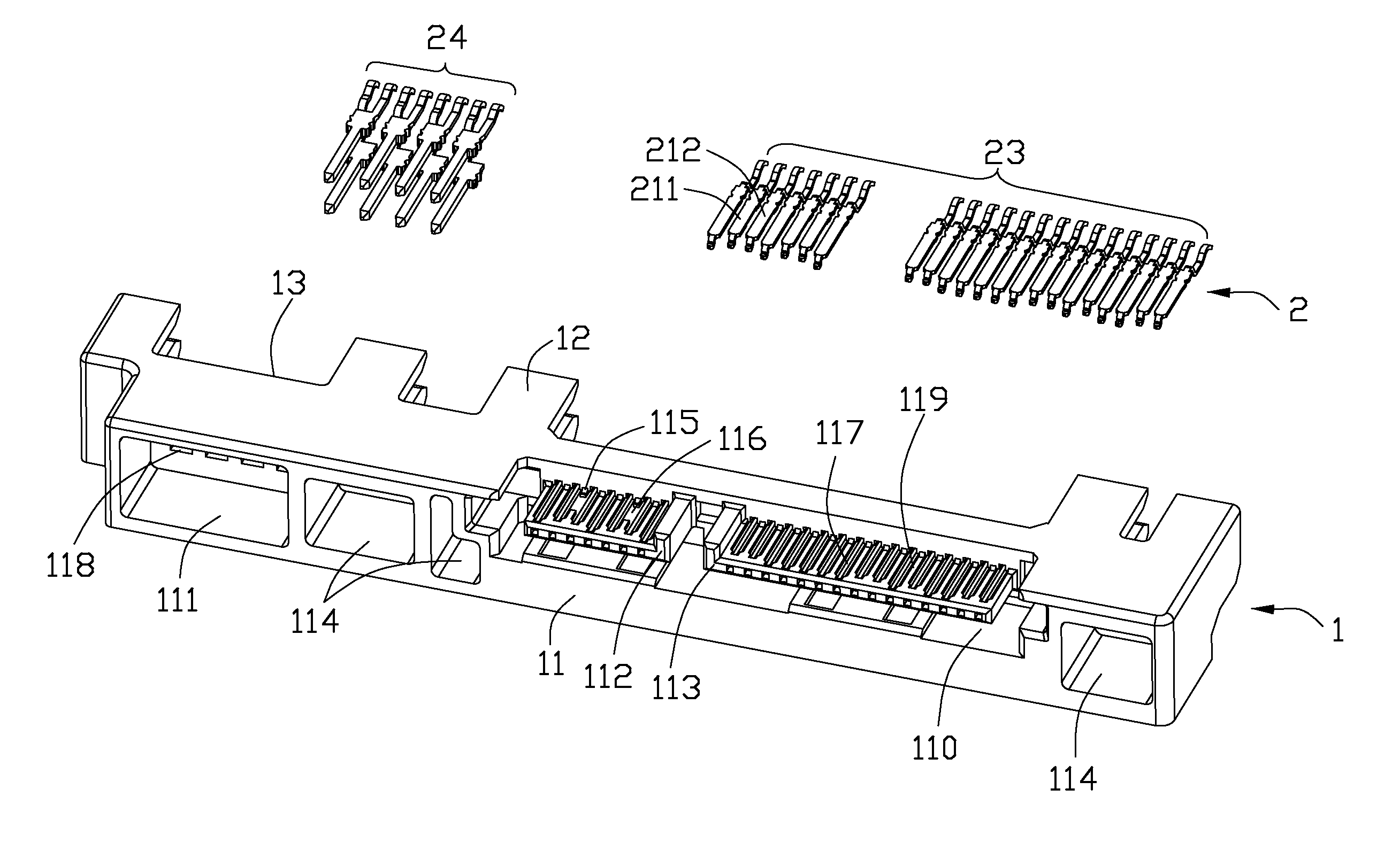
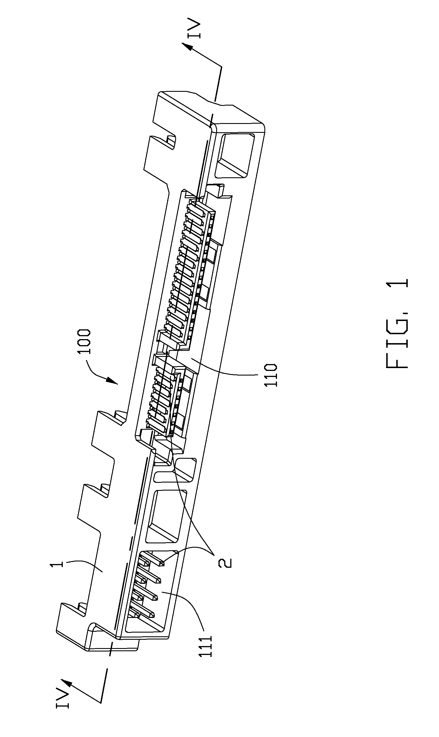
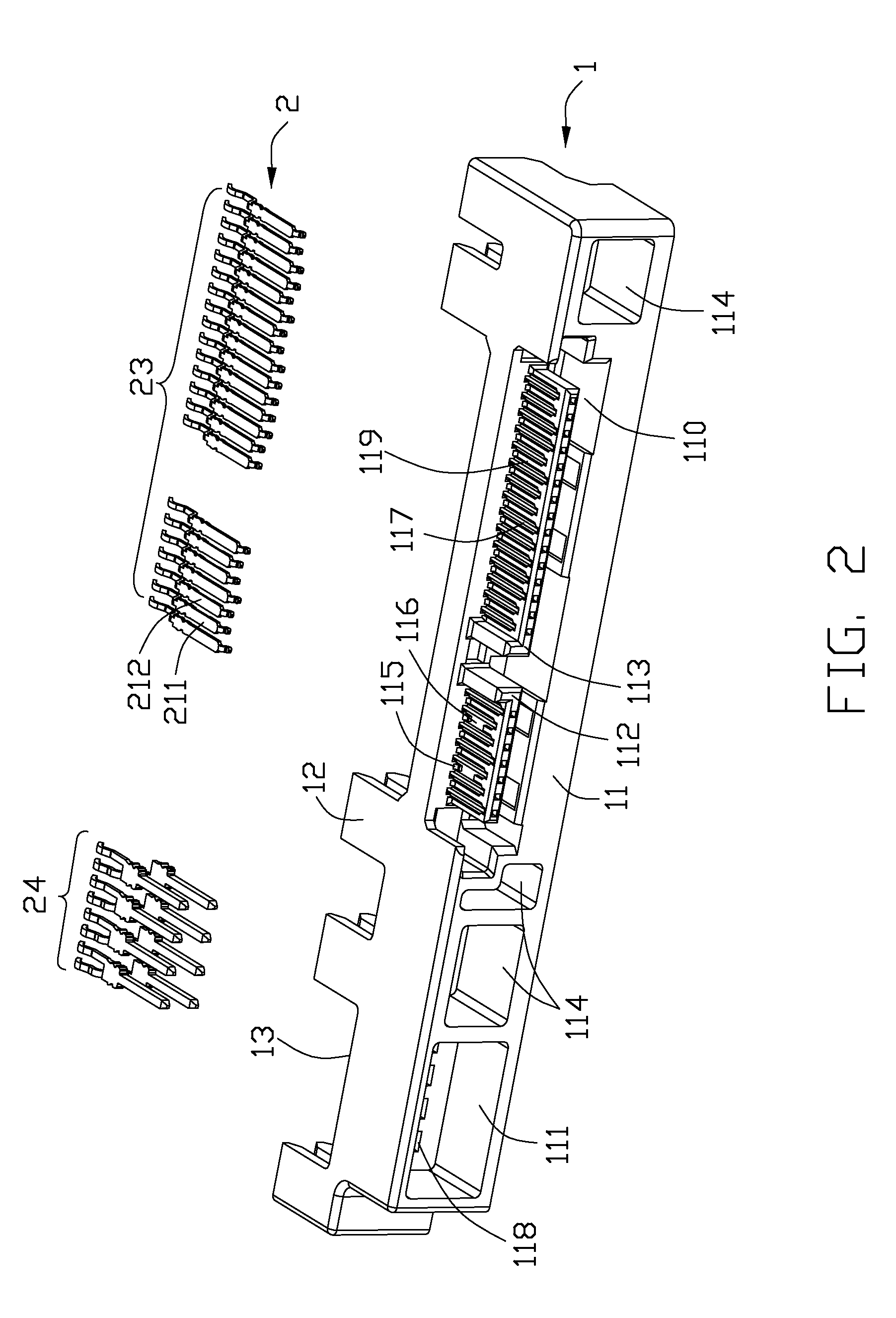
[0018]Referring to FIG. 1, an electrical connector 100 of the present invention is accordance with a Serial Advanced Technology Attachment (SATA) standard. The electrical connector 100 comprises an insulative housing 1 defining two mating ports 110, 111 with a plurality of contact 2 in the mating ports 110, 111.

[0019]Referring to FIGS. 1 and 2, the insulative housing 1 is substantially elongated and integrally formed which has a front mating face 11 for confronting with a complementary connector (not shown), a rear face 13 opposite to the front mating face 11 and a top face 12 perpendicular to the mating face 11. The first mating port 110 extends between the mating face 11 and the rear face 13 and opens upwardly and forwardly. The first mating port 110 defines two similar L-shaped tongue portions 112,113 side by side extending forwardly parallel to the top face 12. The second mating port ...


PUM


Abstract

An electrical connector assembly has an elongated insulative housing and a plurality of signal contacts secured in corresponding passageways defined in the housing. Each signal contact has a retention portion retained in the passageway, a contact portion extending from the retention portion and a soldering portion extending from the retention portion. The contact portion defines a first face exposing an exterior of the passageways and a second face opposite to the first face. Wherein each of signal contacts defines a recess on the second face. The signal contacts become thinner so as to prevent signal contacts from crosstalk and improve high frequency performance.

Description

BACKGROUND OF THE INVENTION[0001]1. Field of the Invention[0002]The present invention generally relates to an electrical connector, and more particularly, to a novel structure of an electrical connector with an improved high frequency performance.[0003]2. Description of Related Art[0004]The usage of electrical connectors with high frequency performance has increased. The undesired signal or loss of signal strength in high frequency electrical connectors become much more frequently. For example, an electrical connector with high frequency signal transmission includes an insulative housing and a plurality of contacts disposed in a plurality of passageways of the insulative housing. Because of electromagnetic wave between each two adjacent contacts, the two contacts are easy to cause undesired signal and crosstalk. When high frequency signals transmit, signals become much weak and electrical connectors can not work normally or cause dummy signal. Thus, an electrical connector with impr...

Claims


Application Information

Patent Timeline
Patent Type & Authority Patents(United States)
IPC IPC(8): H01R12/00
CPCH01R13/41H01R13/65807H01R13/6471H01R13/6474
Inventor ZHU, YU
Owner HON HAI PRECISION IND CO LTD
Why Eureka
Try Eureka