
Method for processing findings entered in a mammogram

a mammogram and findings technology, applied in the field of mammography, can solve the problems of reducing the effective time to be used by the physician for visual viewing and diagnosis of the mammogram, increasing the susceptibility to diagnosis faults, and increasing the number of mammograms to be evaluated

Active Publication Date: 2011-03-29
IMAGE DIAGNOST INT
View PDF5 Cites 6 Cited by
  • Summary
  • Abstract
  • Description
  • Claims
  • Application Information

AI Technical Summary

Benefits of technology

[0012]Embodiments of the invention may provide a method by means of which the location of findings entered in a mammogram relative to the nipple can reliably be determined and be transferred into a findings input mask.
[0015]Treating the object area of a mammogram as two partial areas has the advantage that discontinuities are avoided when transferring findings entered in the mammogram into a findings input mask. Because the unambiguous allocation of the findings to one partial area, it is excluded in particular that findings located in a mammogram approximately at the level of the nipple erroneously are stored for instance as “located above the nipple”, although the findings actually are located just below the nipple. This is essential, as in the transformation and storage of the findings into a clock time model with reference to the nipple, the information “above / below” or “to the right / left” of the nipple determines whether the findings are located in the upper or lower half or in the right or left half of the clock time model. A mislocation can, for instance, lead to the fact that instead of the clock time “12 o'clock” the diametrically opposite clock time “6 o'clock” is stored. Due to an embodiment of the method of the invention and the unambiguous allocation of the findings to a partial area of the breast, this mislocation is excluded.

Problems solved by technology

Regular mammography screening in particular involves the problem that a physician must evaluate a great number of mammograms in a short time.
In conventional evaluation devices it is disadvantageous that the physician is distracted from the image when entering the findings, since the findings input must be performed in the separate findings input window, the effective time to be used by the physician for the visual viewing and diagnosis of the mammogram is reduced thereby, and switching between findings input and viewing leads to an increased susceptibility to faults in diagnosis.
Furthermore, transmission errors can occur, frequently due to the fact that as an essential information during findings input the physician must document the location of the findings in the mammogram and indicate the same by suitable, but frequently inaccurate location indications in the separate findings input window.
One problem, however, which arises here, consists in the fact that the clock time model is discontinuous for findings in the region of the nipple: depending on whether the findings are located just above or below or to the right or left of the nipple, the location indication of the findings in the clock time model will jump from the “top” to the “bottom” or from the “right” to the “left” and vice versa.

Method used


Image

  • Method for processing findings entered in a mammogram
  • Method for processing findings entered in a mammogram
  • Method for processing findings entered in a mammogram

Examples


Embodiment Construction

[0031]As used herein, an element or function recited in the singular and proceeded with the word “a” or “an” should be understood as not excluding plural said elements or functions, unless such exclusion is explicitly recited. Furthermore, references to “one embodiment” of the claimed invention should not be interpreted as excluding the existence of additional embodiments that also incorporate the recited features.

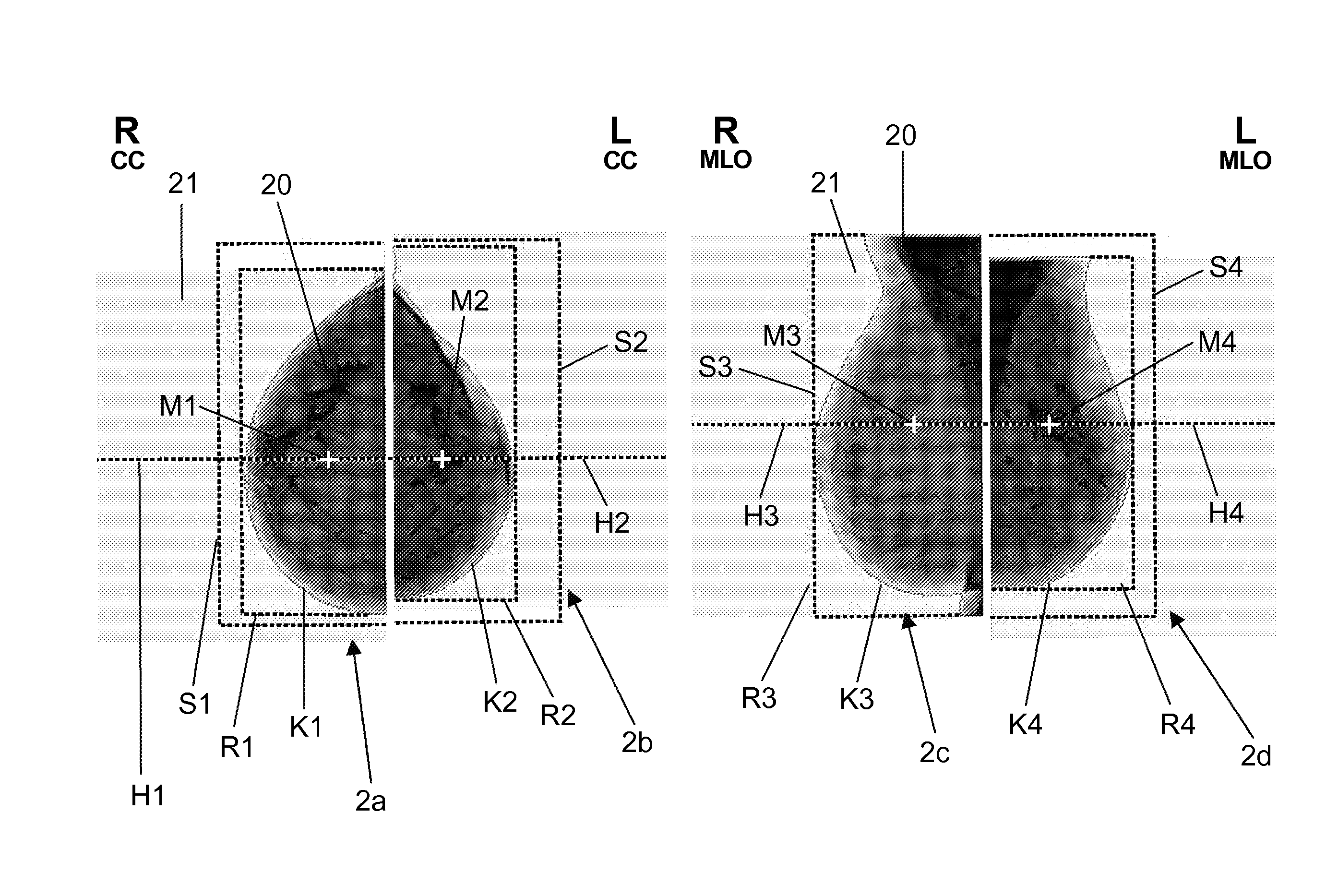
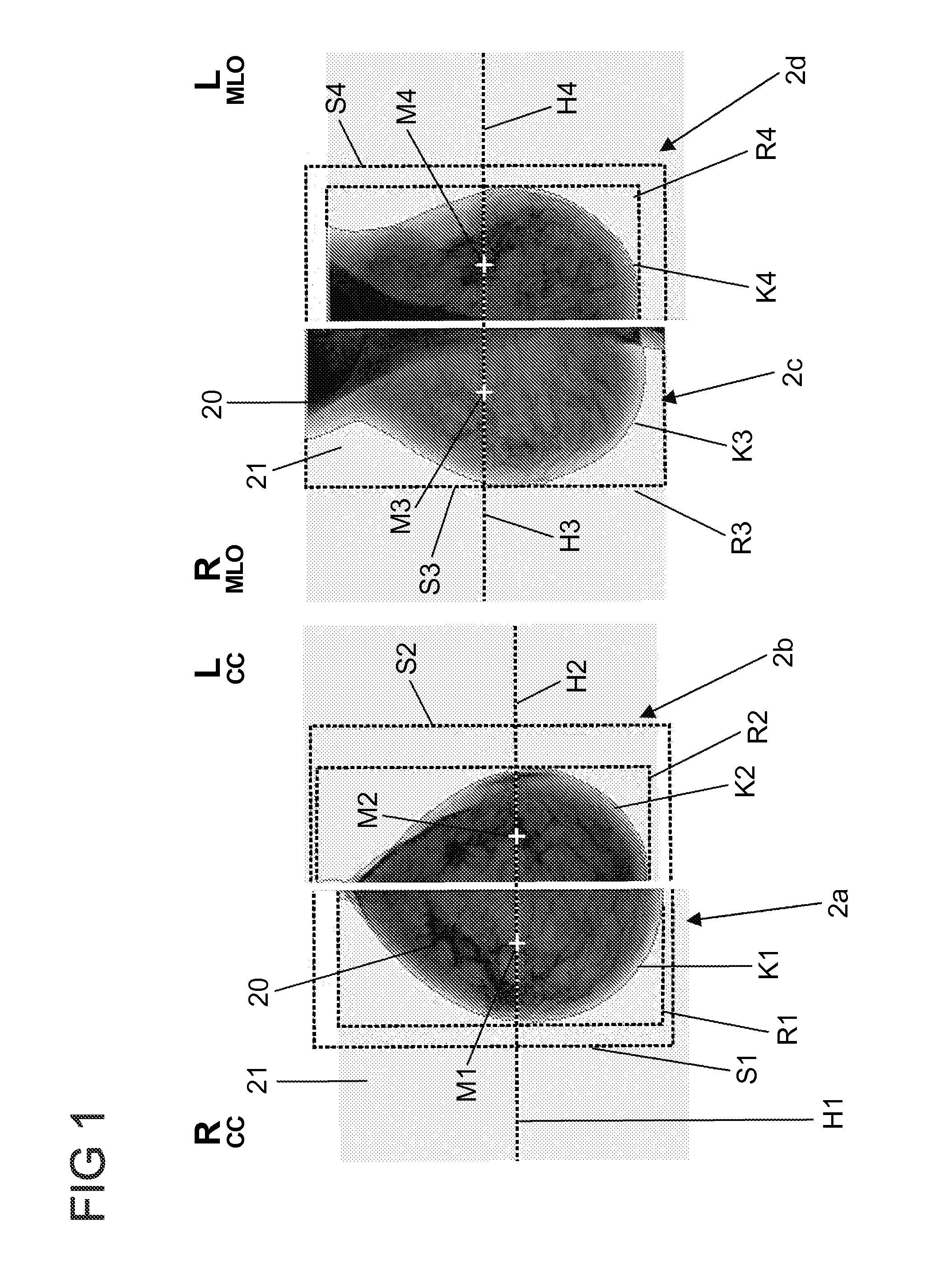
[0032]FIG. 1 shows views of four digitally present mammograms 2a, 2b, 2c, 2d, which are displayed on an evaluation device. The digital mammograms 2a, 2b, 2c, 2d represent different views of a breast imaged in an object area 20 against a background region 21, namely mediolateral-oblique (MLO) mammograms 2c, 2d and cranio-caudal mammograms 2a, 2b of a left (L) and a right (R) breast. The mammograms 2a, 2b, 2c, 2d can have been generated using a direct-digital X-ray apparatus or digitized subsequently, when using an analogue X-ray apparatus.

[0033]The evaluation device in part...


PUM


Abstract

A method for processing findings entered in a mammogram. A digital mammogram is displayed via an evaluation device. Via an input device the findings are entered directly into the displayed mammogram and are automatically transferred from the mammogram into a findings input mask. To transfer the findings from the mammogram into the findings input mask, a contour line of an object area surrounding an object of the mammogram is determined. An object area of the mammogram is divided into two partial areas. Each partial area is imaged onto an allocated mask region of the findings input mask. The entered findings are allocated to one of the partial areas and are transferred into the findings input mask with reference to the allocated partial area. In this manner, a location of findings entered in a mammogram relative to the nipple can reliably be determined and transferred into a findings input mask.

Description

CROSS-REFERENCE TO RELATED APPLICATIONS[0001]This application claims priority under 35 U.S.C. §119(a)-(d) or (f) to prior-filed, co-pending GERMAN patent application serial number 2008035566.6, filed on Jul. 30, 2008, which is hereby incorporated by reference in its entirety.STATEMENT REGARDING FEDERALLY SPONSORED RESEARCH OR DEVELOPMENT[0002]Not ApplicableNAMES OF PARTIES TO A JOINT RESEARCH AGREEMENT[0003]Not ApplicableREFERENCE TO A SEQUENCE LISTING, A TABLE, OR COMPUTER PROGRAM LISTING APPENDIX SUBMITTED ON COMPACT DISC[0004]Not ApplicableBACKGROUND OF THE INVENTION[0005]1. Field of the Invention[0006]The field of the invention relates to mammography generally, and more particularly to a method for processing findings entered in a mammogram.[0007]2. Description of Related Art[0008]In such a method for processing findings entered in a mammogram, as it is known for instance from DE 10 2006 021 037 A1, a digital mammogram is displayed via an evaluation device, the findings are dire...

Claims


Application Information

Patent Timeline
Patent Type & Authority Patents(United States)
IPC IPC(8): G06K9/00
CPCA61B6/463G06T11/206A61B6/502A61B2019/505G06T2210/41A61B10/0041A61B2034/105
Inventor HEINLEIN, PETERBLUMENTHAL, MARCODIMA, ANCA
Owner IMAGE DIAGNOST INT
Learn More