Variable valve mechanism for engine

a valve mechanism and variable technology, applied in the direction of mechanical control devices, process and machine control, instruments, etc., can solve the problems of hindering the and achieve the effect of ensuring smooth operation of the rocker arm and reducing engine siz

Active Publication Date: 2011-04-05
MITSUBISHI MOTORS CORP
View PDF3 Cites 4 Cited by
  • Summary
  • Abstract
  • Description
  • Claims
  • Application Information

AI Technical Summary

Benefits of technology

[0006]It is therefore an object of the invention to provide a variable valve mechanism for an engine that can secure smooth operating performance of the rocker arms while allowing for downsizing of the engine.

Problems solved by technology

However, when the rocker arm abuts against the cylinder head, friction occurs at a contact part therebetween at the time of rocker arm operation, and thus a smooth operation of the rocker arm is hindered.

Method used


Image

  • Variable valve mechanism for engine
  • Variable valve mechanism for engine
  • Variable valve mechanism for engine

Examples


first embodiment

[0024]A first embodiment where a variable valve mechanism for an engine according to the present invention is applied to an engine where a plurality of cylinders are disposed in series along the front and rear direction of an engine body will be described by using FIG. 1 to FIG. 5.

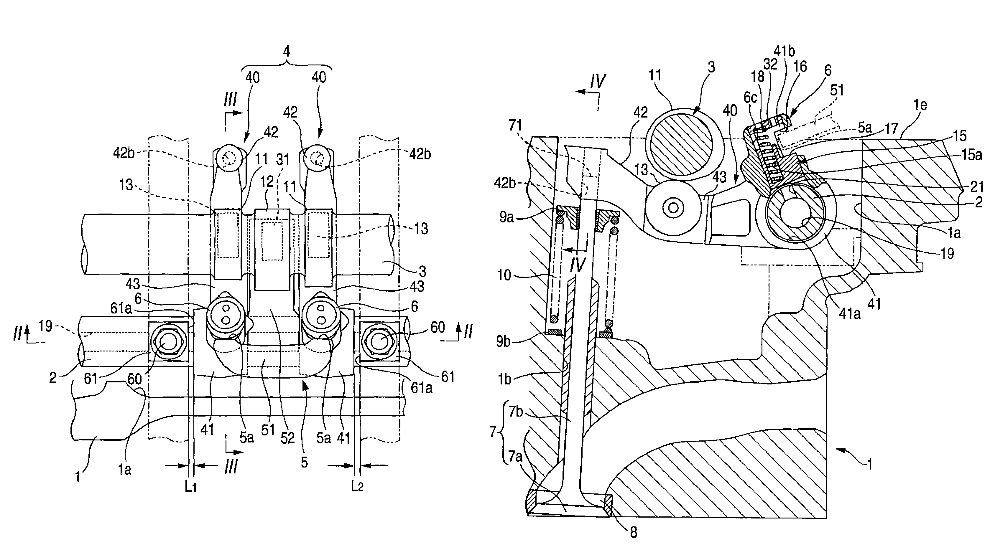
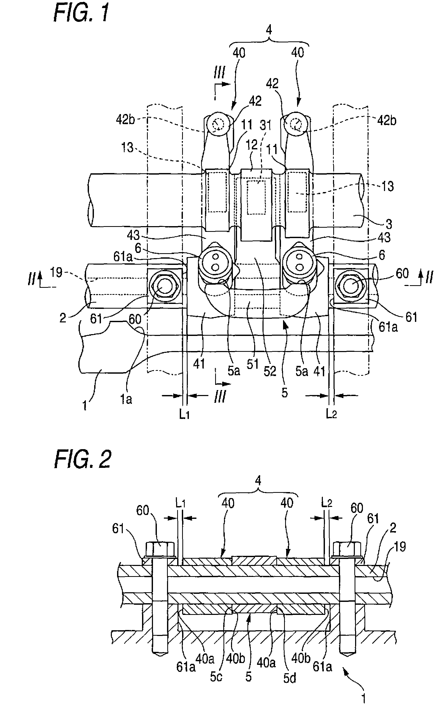
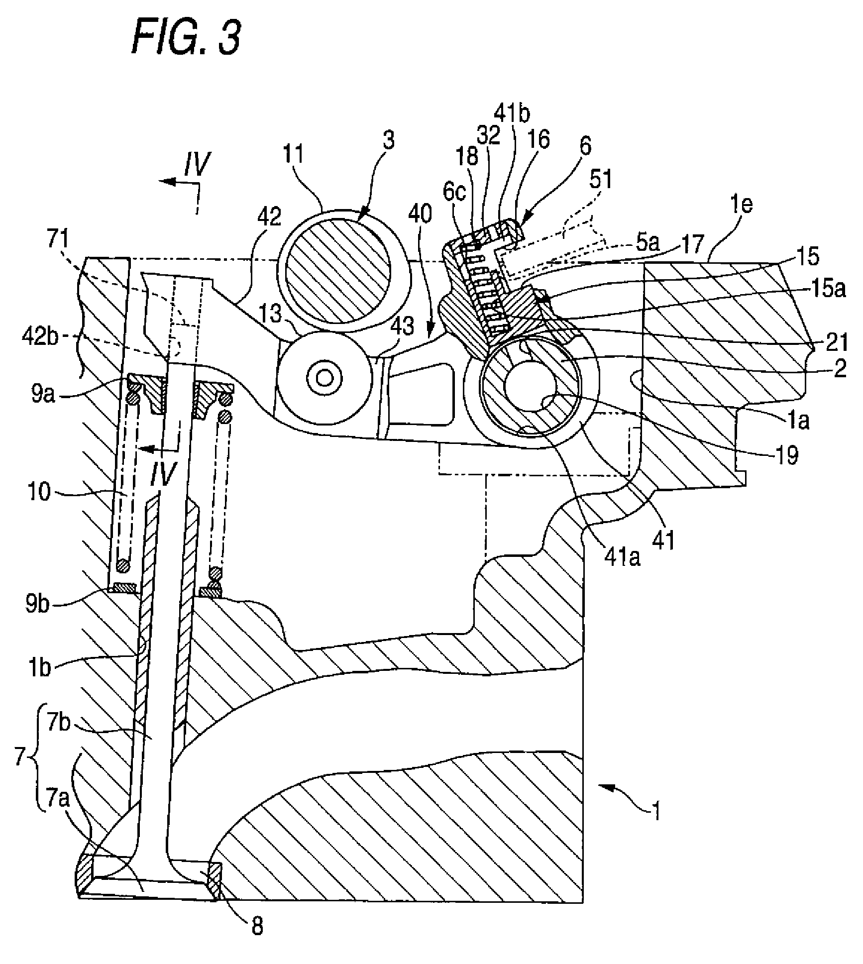
[0025]FIG. 1 is a plan view showing a rocker arm provided corresponding to the intake side of one of a plurality of cylinders in an internal-combustion cylinder head including a variable valve mechanism for an engine, FIG. 2 is a view taken along an arrow line II-II in FIG. 1, FIG. 3 is a view taken along an arrow line III-III in FIG. 1, and FIG. 4 is a view taken along an arrow line IV-IV in FIG. 3. FIG. 5 is an explanatory view showing a state when processing a cylinder head in which a variable valve mechanism for an engine is provided.

[0026]As shown in FIG. 1 to FIG. 3, a variable valve mechanism for an engine according to the present embodiment includes a rocker shaft 2, a camshaft 3, rocker arms (a fi...

second embodiment

[0047]A second embodiment where a variable valve mechanism for an engine according to the present invention is applied to an engine where a plurality of cylinders are disposed in series along the front and rear direction of an engine body will be described in detail by using FIG. 6 and FIG. 7.

[0048]FIG. 6 is a plan view showing a rocker arm provided corresponding to the intake side of one of a plurality of cylinders in an internal-combustion cylinder head including a variable valve mechanism for an engine, and FIG. 7 is a view taken along an arrow line VII-VII in FIG. 6.

[0049]A variable valve mechanism for an engine according to the present embodiment is a mechanism modified in the other arm body (the first arm body disposed at the right side of the second rocker arm 5 in FIG. 6 and FIG. 7) of the pair of first arm bodies that the variable valve mechanism for an engine according to the first embodiment described above includes, and a mechanism including the same members (for example...


PUM


Abstract

A variable valve mechanism for an engine includes: a rocker shaft; a first rocker arm rotatably supported by the rocker shaft, for transmitting displacement of a first cam to a valve; a second rocker arm rotatably supported by the rocker shaft, for transmitting a displacement of a second cam to the valve; and a switching mechanism for switching a transmitting state and a non-transmitting state. The first rocker arm has a pair of first arm portions and a recess portion in which an upper end of the valve is inserted at an end portion of each of the first arm portions. The second rocker arm has a second arm portion disposed between the first arm portions. The first rocker arm is restricted from movement in an axis direction of the rocker shaft when an inner sidewall of the recess portion is in contact with the upper end of the valve. The second rocker arm is restricted from movement in the axis direction when the second arm portion is in contact with the first rocker arm.

Description

BACKGROUND OF THE INVENTION[0001]The present invention relates to a variable valve mechanism for an engine.[0002]In an engine, improvement in both output and fuel efficiency is realized by assembling a cam-switching variable valve device onto a valve operating system. The variable valve device is a device for switching the opening / closing timing of a valve and the lifting amount thereof by switching cams. In the variable valve device, a plurality of types of cams different in cam profile from each other are provided side by side on a camshaft. And, by selectively switching rocker arms that follow these cams, displacement of the cam to be transmitted to the valve is changed.[0003]In such a case that an engine is mounted in an automobile, with the aim of making the cylinder head itself compact while avoiding engine components, the camshaft is disposed obliquely above the rocker shaft, for example. Such a variable valve device assembled on an engine has been disclosed in, for example, ...

Claims


Application Information

Patent Timeline
Patent Type & Authority Patents(United States)
IPC IPC(8): F01L1/18
CPCF01L1/185F01L1/267F01L13/0036F01L1/053Y10T74/2107F01L2105/00Y10T74/20882F01L2001/186F01L2305/00F01L1/18F01L13/00
Inventor YOSHIHARA, AKIRATAKAHASHI, YUICHIKOTSUJI, KENTAKUTSUNA, YASUNORIOHTA, AKIRAISHII, SATORU
Owner MITSUBISHI MOTORS CORP
Why Eureka
Try Eureka