Impact energy absorber and fabrication method thereof

Inactive Publication Date: 2011-04-05
MAZDA MOTOR CORP
View PDF4 Cites 7 Cited by
  • Summary
  • Abstract
  • Description
  • Claims
  • Application Information

AI Technical Summary

Benefits of technology

The present invention was conceived under the above circumstances and may advantageously provide an impact energy absorber which can be stably deformed in the tube axis direction of the main body without causing buckling deformation in the tubular main body and which has excellent handleability.
By combining the outer and inner premolded bodies and the molten material of the metal into a composite using this fabrication method, the deformable portion and the outer and inner deformation controlling portions can readily be integrally molded. An impact energy absorber which is capable of stable deformation in the tube axis direction of the main body and which has excellent handleability can be readily produced.

Problems solved by technology

However, in the above structure, there is a probability that, when a compression load is input to the main body in the tube axis direction so that the first portion and the second portion are disengaged at the engagement portion and the first portion is pushed into the inner hollow of the second portion, the first portion is not smoothly pushed into the inner hollow of the second portion, and the first portion or second portion undergoes buckling deformation.
Therefore, it is difficult to stably deform the impact energy absorber.
In this case, a device which can absorb a compression load such as produced by collision of vehicles requires a considerably large number of first and second portions.
However, when the impact energy absorber has a considerably large number of first and second portions, there is a probability that the first or second portions fall off during transportation of the impact energy absorber or during assemblage of the absorber into a vehicle, or the like.
Thus, the impact energy absorber disadvantageously has poor handleability.

Method used


Image

  • Impact energy absorber and fabrication method thereof
  • Impact energy absorber and fabrication method thereof
  • Impact energy absorber and fabrication method thereof

Examples


example embodiment 1

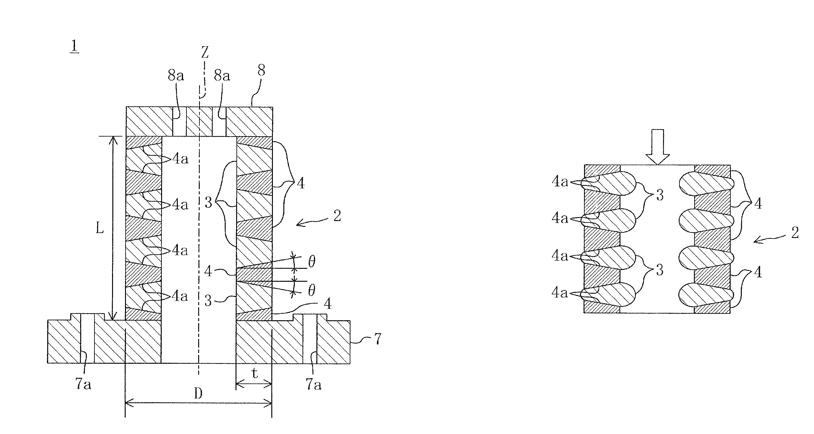
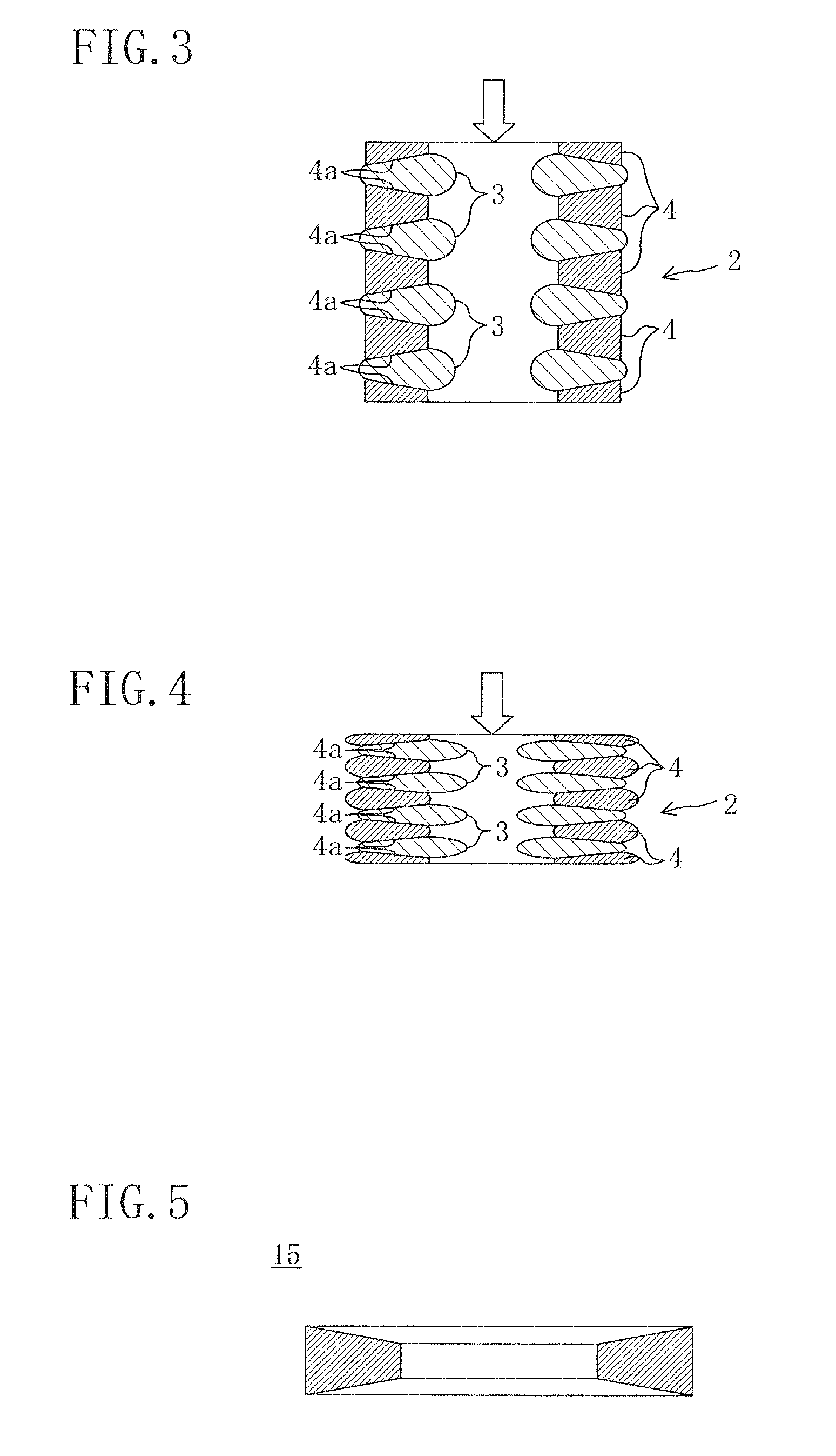
FIG. 1 shows an impact energy absorber 1 of example embodiment 1. The impact energy absorber 1 has a main body 2 which is tubular (specifically, cylindrical in this example embodiment) and which is adapted to absorb a compression load input to the main body 2 in the direction of tube axis Z (vertically downward direction in FIG. 1).

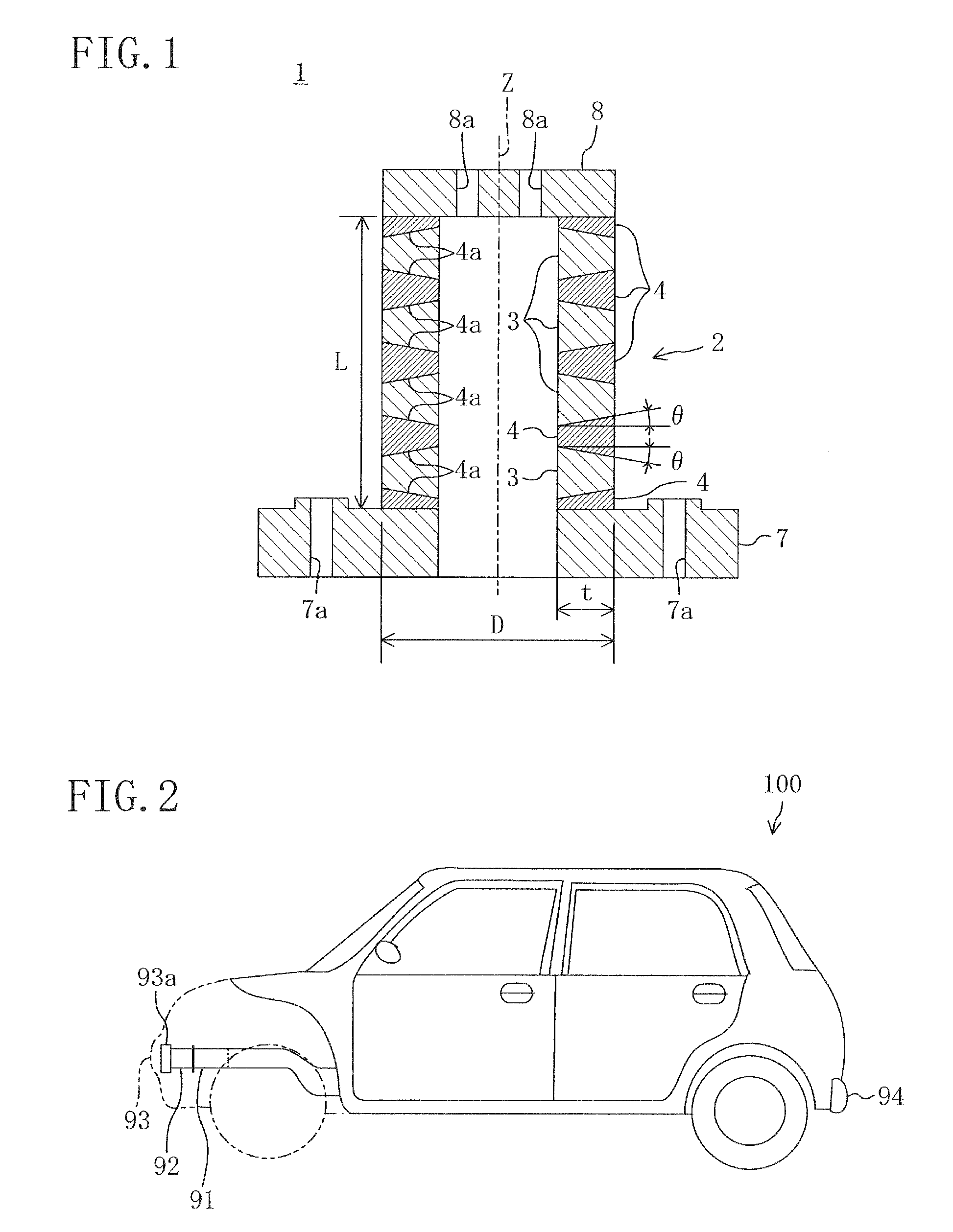
In this example embodiment, as shown in FIG. 2, at both sides of the front part of a vehicle 100 with respect to the vehicle width direction, the impact energy absorber 1 is used as crush cans 92 which are interposed between the front ends of right and left front side frames 91 extending in the lengthwise direction of the vehicle 100 and the right and left ends of a bumper reinforcement 93a extending in the vehicle width direction in a front bumper 93. In this case, the impact energy absorber 1 is placed such that the direction of tube axis Z is coincident with the lengthwise direction of the vehicle 100. In the case of a head-on collision of the vehicle ...

example embodiment 2

FIG. 9 shows example embodiment 2 in which the shape of the deformation controlling portions 4 is different from that of example embodiment 1.

Specifically, in this example embodiment, the exterior shape of each deformation controlling portion 4 in the main body 2 of the impact energy absorber 1 (the shape of the slope surface 4a) is the same as that of example embodiment 1. However, three pieces of the deformation controlling portions 4, rather than two pieces of the deformation controlling portions 4 placed at the both axial ends of the main body 2 with respect to the direction of tube axis Z, have trenches 4b which are recessed from the outer perimeter surface (the surface which constitutes the outer perimeter surface of the main body) toward the inner perimeter surface and which run along the entire perimeter of the deformation controlling portions 4. In the trenches 4b, the deformable portions 3 are provided. Also, as in example embodiment 1, the deformable portions 3 are provid...

example embodiment 3

FIG. 11 shows example embodiment 3, in which a plurality of outer deformation controlling portions 5 are provided in the outer perimeter surface of the main body 2, and a plurality of inner deformation controlling portions 6 are provided in the inner perimeter surface of the main body 2, instead of the deformation controlling portions 4 of example embodiment 1.

Specifically, in this example embodiment, the main body 2 of the impact energy absorber 1 is integrally composed of a deformable portion 3, a plurality of outer deformation controlling portions 5 which are placed in the outer perimeter surface of the main body 2 at a plurality of positions along the direction of tube axis Z in an annular arrangement along a perimeter direction of the main body 2 and which are adapted to control the direction of the plastic deformation of the deformable portion 3, and a plurality of inner deformation controlling portions 6 which are placed in the inner perimeter surface of the main body 2 at a ...


PUM

PropertyMeasurementUnit
Melting pointaaaaaaaaaa
Deformation enthalpyaaaaaaaaaa
Volume ratioaaaaaaaaaa

Abstract

A main body of an impact energy absorber is formed by integrally molding a deformable portion and a plurality of deformation controlling portions which are adapted to control the direction of plastic deformation of the deformable portion. The deformation controlling portions have such a configuration and shape that, when a compression load equal to or greater than a predetermined value is input to the main body in a tube axis direction, the deformable portion undergoes plastic deformation in at least one of a radially outward direction and a radially inward direction of the main body concurrently with the compressive plastic deformation in the tube axis direction.

Description

CROSS-REFERENCE TO RELATED APPLICATIONSThis application claims priority from Japanese Patent Applications Nos. 2008-205197, 2008-205202, and 2008-205204 filed on Aug. 8, 2008, which are hereby incorporated by reference in its entirety for all purposes.BACKGROUNDThe technology disclosed in this specification relates to an impact energy absorber which absorbs a compression load input to a tubular main body in the tube axis direction and which is suitable for a crush can of a vehicle, and the like, and to a fabrication method of the impact energy absorber.As conventionally known in the art, a vehicle is provided with a crush can as an impact energy absorber at, for example, the front end of the front side frame or the rear end of the rear side frame for absorbing impact energy (impact compression load) produced by a head-on or nose-to-tail collision of vehicles.For impact energy absorbers, such as aforementioned crush cans, and the like, various improvements have been proposed to incre...

Claims


Application Information

Patent Timeline
IPC IPC(8): B62D25/08B60R19/34
CPCB22D17/00B22D19/00B60R19/34F16F7/12B22D19/02Y10T29/49826
Inventor NISHIGUCHI, KATSUYAUEOKA, TOSHITSUGUYAMAMOTO, KENICHIMURASE, KENJI
Owner MAZDA MOTOR CORP
Why Eureka
Try Eureka