
Fundus camera

a camera and camera body technology, applied in the field offundus cameras, can solve the problems of low color rendering property, poor color development in comparison with a conventional halogen lamp or a xenon tube, and only consumes a small amount of power, and achieves good color development, natural color, and high light use efficiency.

Inactive Publication Date: 2011-04-05
CANON KK
View PDF5 Cites 5 Cited by
  • Summary
  • Abstract
  • Description
  • Claims
  • Application Information

AI Technical Summary

Benefits of technology

The present invention is about a fundus camera that can capture images of the eye fundus with good color development and natural color. The camera has a high efficiency of using light. The camera includes an illumination unit that irradiates the eye fundus with visible light from a position conjugate with the anterior eye portion of the eye to be examined. The imaging unit takes an image of the eye fundus with the light emitted from the illumination unit and reflected from the eye fundus. The illumination unit includes a blue LED chip and a fluorescent member that is excited by the blue LED chip and emits fluorescence. The fluorescent member is irradiated again with a part of the light reflected by the optical element.

Problems solved by technology

The white LED emits white light and consumes only a small amount of power and generates a small amount of heat.
Accordingly, there is a problem in that a color rendering property is lowered.
If photographing is performed using the above-described white LED as a photographing light source, color development is bad in comparison with a conventional halogen lamp or a xenon tube.
Therefore, an image of the eye fundus shows an unnatural color and use efficiency of the light also deteriorates.
However, in this case, the use efficiency of the light deteriorates.
Even in the case of the white LED which has a high color rendering property, some light passes through the fluorescent member without exciting the fluorescent member as for light emitted from the LED and energy use efficiency is low.

Method used


Image

  • Fundus camera
  • Fundus camera
  • Fundus camera

Examples


Embodiment Construction

[0029]Various exemplary embodiments, features, and aspects of the invention will be described in detail below with reference to the drawings.

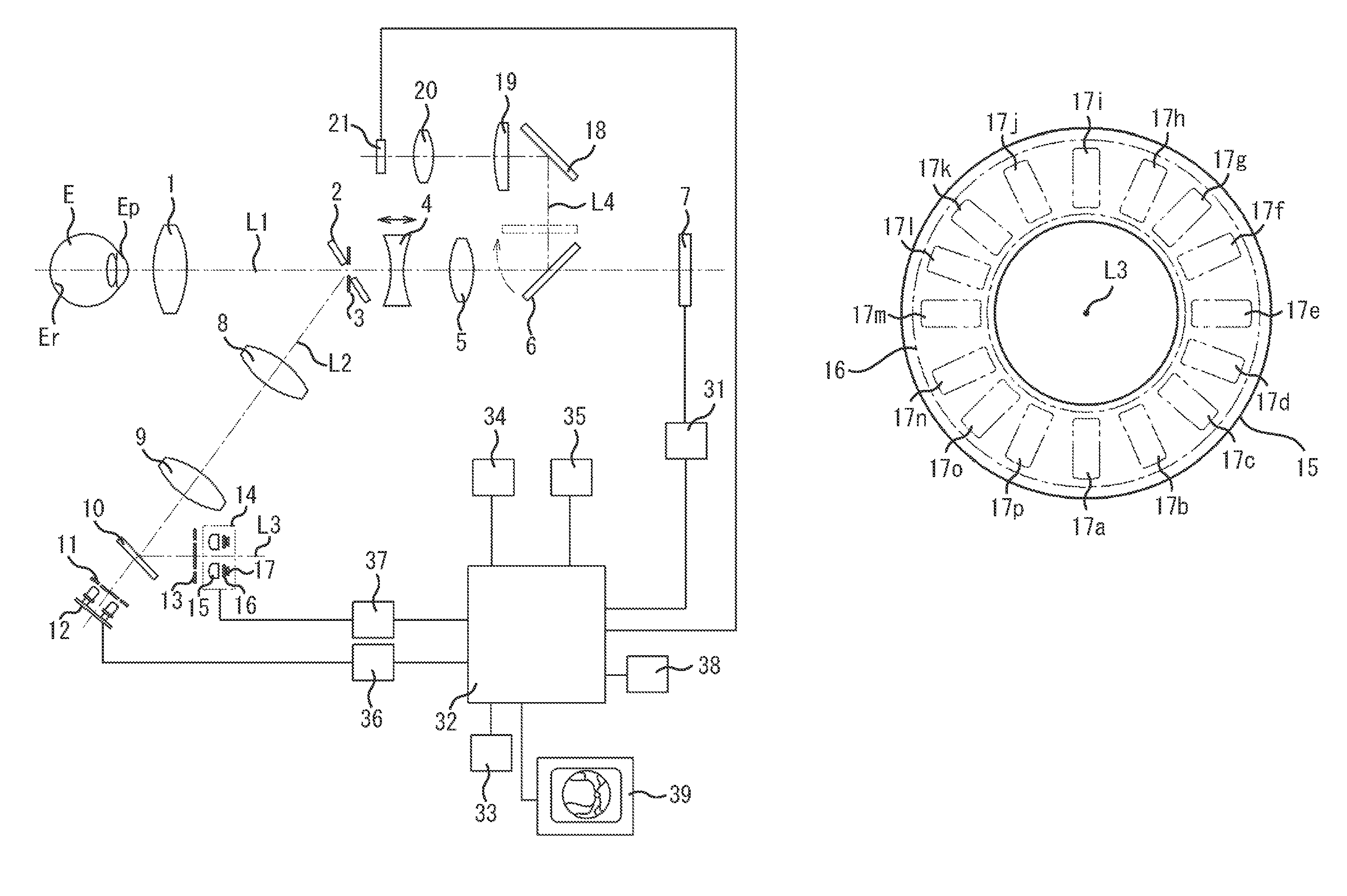
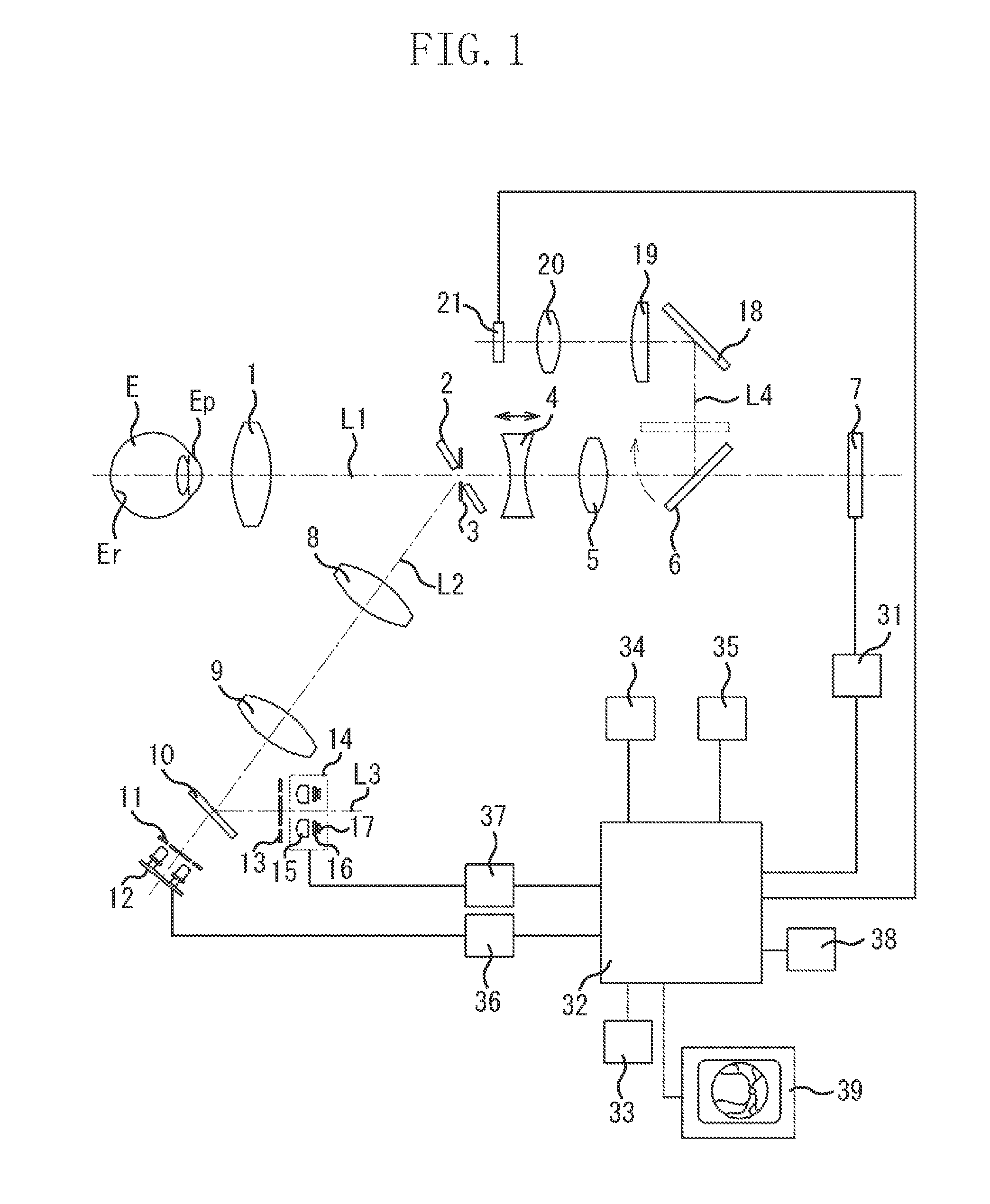
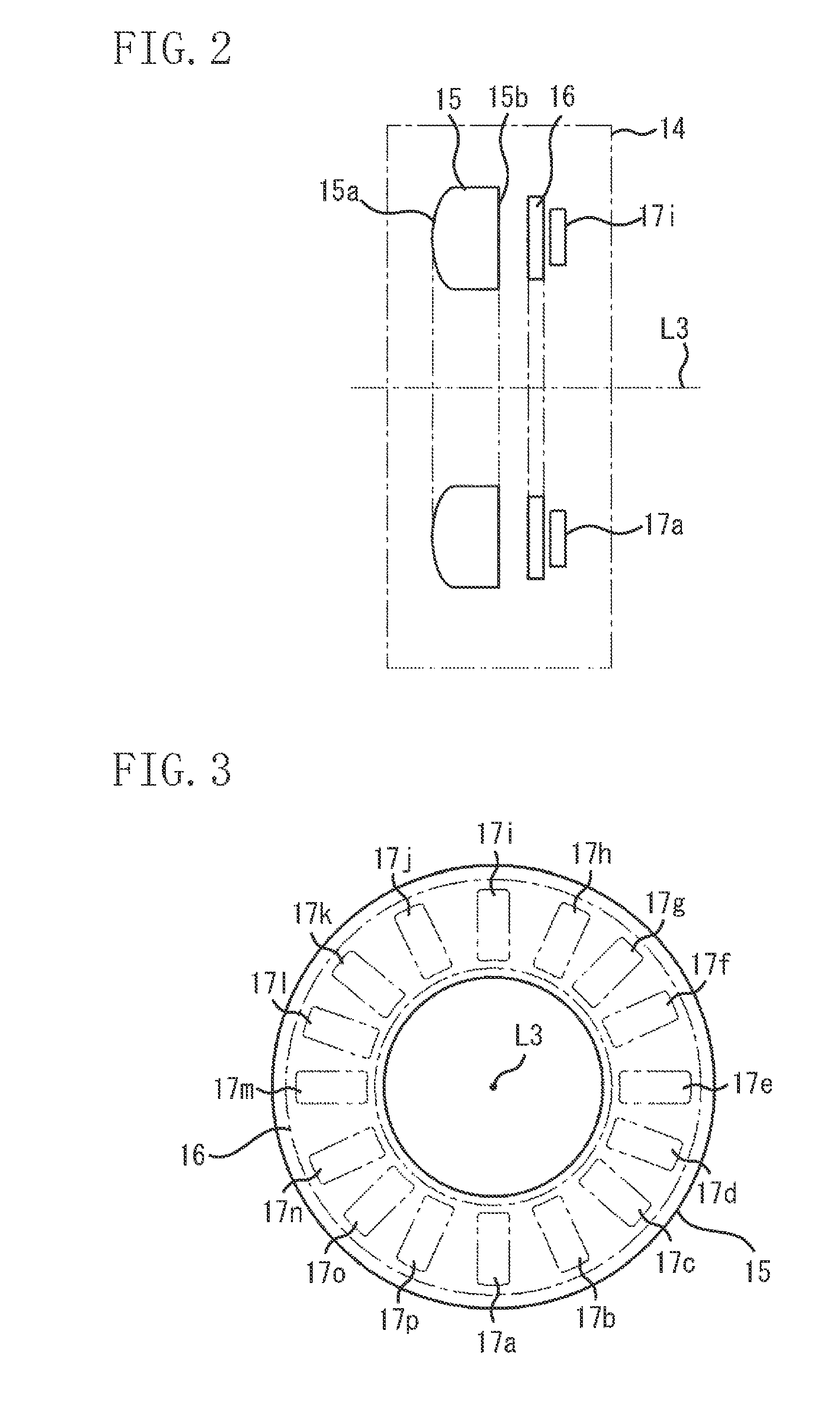
[0030]FIG. 1 illustrates a structure of a non-mydriatic fundus camera according to a first exemplary embodiment. FIG. 2 is an enlarged cross-sectional view of a white LED unit. FIG. 3 is a front view of the white LED unit. FIG. 4 is an enlarged view of a part of the white LED unit.

[0031]An eye fundus imaging optical system includes an objective lens 1, a perforated mirror 2, a photographic diaphragm 3, a focusing lens 4, an imaging lens 5, a flip-up mirror 6, and an image sensor 7 that are sequentially arranged on an optical axis L1 on the front side of an eye E to be examined. The focusing lens 4 is movable in a direction of an optical path, and the image sensor 7 is sensitive to visible light and mainly photographs a still image.

[0032]An eye fundus observing-illumination optical system includes lenses 8 and 9, a dichroic mirror 10, a ring dia...


PUM


Abstract

A fundus camera includes an illumination unit which includes an optical element configured to irradiate an eye fundus with visible light from a position conjugate with an anterior eye portion of an eye to be examined, and an imaging unit configured to take an image of the eye fundus with light which is emitted from the illumination unit and reflected from the eye fundus, wherein the illumination unit includes a blue LED chip and a fluorescent member that is excited by light emitted from the blue LED chip and emits fluorescence, and the fluorescent member is irradiated again with apart of the light reflected by the optical element.

Description

BACKGROUND OF THE INVENTION[0001]1. Field of the Invention[0002]The present invention relates to a fundus camera that includes a light-emitting diode for emitting white light as a light source for illuminating a fundus of an eye to be examined.[0003]2. Description of the Related Art[0004]Conventionally, a halogen lamp that emits steady light as an observation light source and a xenon tube that emits pulse light as a photographing light source have been used as a light source of a fundus camera.[0005]Further, an illumination device which uses a white light-emitting diode (LED) as a light source has come to be used instead of a fluorescent lamp or an incandescent lamp. The white LED emits white light and consumes only a small amount of power and generates a small amount of heat. Also in an ophthalmologic apparatus such as a fundus camera, an infrared LED has been used as an auxiliary light source or an index projecting light source for alignment.[0006]Further, a white LED has been emp...

Claims


Application Information

Patent Timeline
Patent Type & Authority Patents(United States)
IPC IPC(8): A61B3/14
CPCA61B3/14A61B3/12
Inventor IWANAGA, TOMOYUKIWADA, MANABUTANAKA, SHINYA
Owner CANON KK
Learn More