Loudspeaker apparatus

a technology for loudspeakers and amplifiers, applied in the direction of transducer casings/cabinets/supports, stereophonic arrangments, electrical transducers, etc., can solve the problems of poor conversion efficiency, insufficient output sound volume, and increased number of loudspeakers, so as to achieve efficient practical use

Inactive Publication Date: 2011-04-05
YAMAHA CORP
View PDF33 Cites 7 Cited by
  • Summary
  • Abstract
  • Description
  • Claims
  • Application Information

AI Technical Summary

Benefits of technology

[0017]An object of the invention is to provide a loudspeaker apparatus capable of providing power and a scale which are optimal, while maintaining the configuration of a line array loudspeaker which is effective in practical use.
[0024]According to the above-described configurations, since audio signals of a plurality of systems are assigned by being distributed to a plurality of loudspeaker blocks, it is possible to secure a large output power as a whole while retaining the configuration of a line array loudspeaker which is effective in practical use in the respective audio signals. In addition, the disadvantages occurring when a plurality of signals are outputted from the same loudspeaker do not occur, such as the intermodulation distortion and the disappearance of antiphase signals due to addition thereof. Further, if the loudspeaker blocks are arranged in a line array form, it is possible to draw out power which is efficient as compared with a planar loudspeaker array using a two-dimensional window function.
[0025]As the grouped loudspeaker blocks are partially stacked, it is possible to arbitrarily realize the number of sound connection signals and the output power which are required for the system, while retaining the configuration of the line array loudspeaker which is efficient in the practical use.
[0026]By configuring the system by stacking units, flexible and rich lineup system can be made flexible and rich lineup system can be made in the design and manufacture of one unit. In addition, since the system can be split into units, it is possible to efficiently provide maintenance including the manufacture, transport, and analysis.
[0027]In the case where an audio beam is formed by the loudspeaker array, the maximum frequency is defined by the pitch (interval) between the loudspeaker elements, and the minimum frequency is defined by the entire width of the loudspeaker row. As the high range signals are outputted from the plural-stage loudspeaker rows arranged in a zigzag form, the pitch (interval) between the loudspeaker elements can be made virtually narrow, and the directivity control characteristics for the high range can be improved. In addition, as the low range signals are outputted by using the entire loudspeaker row whose width is wider than that for the high range, the directivity of the audio beam can be improved. As a result, it is possible to alleviate the deviation in the directivity due to the frequency band.
[0029]In addition, since the loudspeaker block is constructed by a line array in the form of the horizontal row, it is possible to configure a loudspeaker apparatus having power and a scale which are optimal for the system, while retaining the characteristic features of the line array loudspeaker which is efficient in the practical use.

Problems solved by technology

However, this system has the following problems.
However, if the loudspeaker is made compact to make the pitch short, the inputtable power is small, and the conversion efficiency is poor, so that there has been a problem in that the output sound volume becomes insufficient.
In addition, while the loudspeaker is made compact and the pitch is made small to control a wide frequency band, if the array width is made large, the number of loudspeakers must be increased, so that there has been a problem in that the apparatus becomes large in size.
If an attempt is made to provide three-dimensional control by arranging the loudspeakers in a planar form, there has been a problem in that the apparatus becomes larger in scale.
Furthermore, if a plurality of users are listening with different postures, it has impossible to allow all the users to listen with the same sound quality.
Accordingly, it is conceivable to provide beam control only in the horizontal direction by the line array; however, if the line array is adopted, the number of loudspeaker elements decreases, so that the input power still remains as a problem.
The input power of a popular full-range loudspeaker of 3 cm or less is 2 W or thereabouts, and if 20 such loudspeakers are arranged as a line array, the input power totals only 40 W. Although this power presents no problem as an ordinary television loudspeaker, it is insufficient as the total power for a multi-channel audio loudspeaker.

Method used


Image

  • Loudspeaker apparatus
  • Loudspeaker apparatus
  • Loudspeaker apparatus

Examples


Embodiment Construction

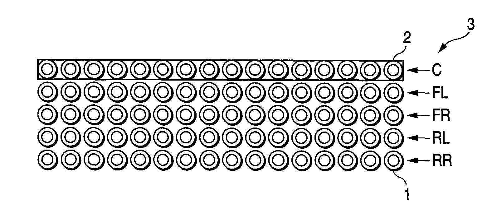
[0042]Referring to the drawings, a description will be given of the embodiments of the invention. It should be noted that in the embodiments described below the loud speaker elements refer to individual loudspeakers, and a loudspeaker array means one which is constructed by arranging a plurality of loudspeaker elements. In additions a loudspeaker block is a section which is formed by a portion or the whole of the loudspeaker array, and an audio signal for each channel or each frequency band is inputted thereto.

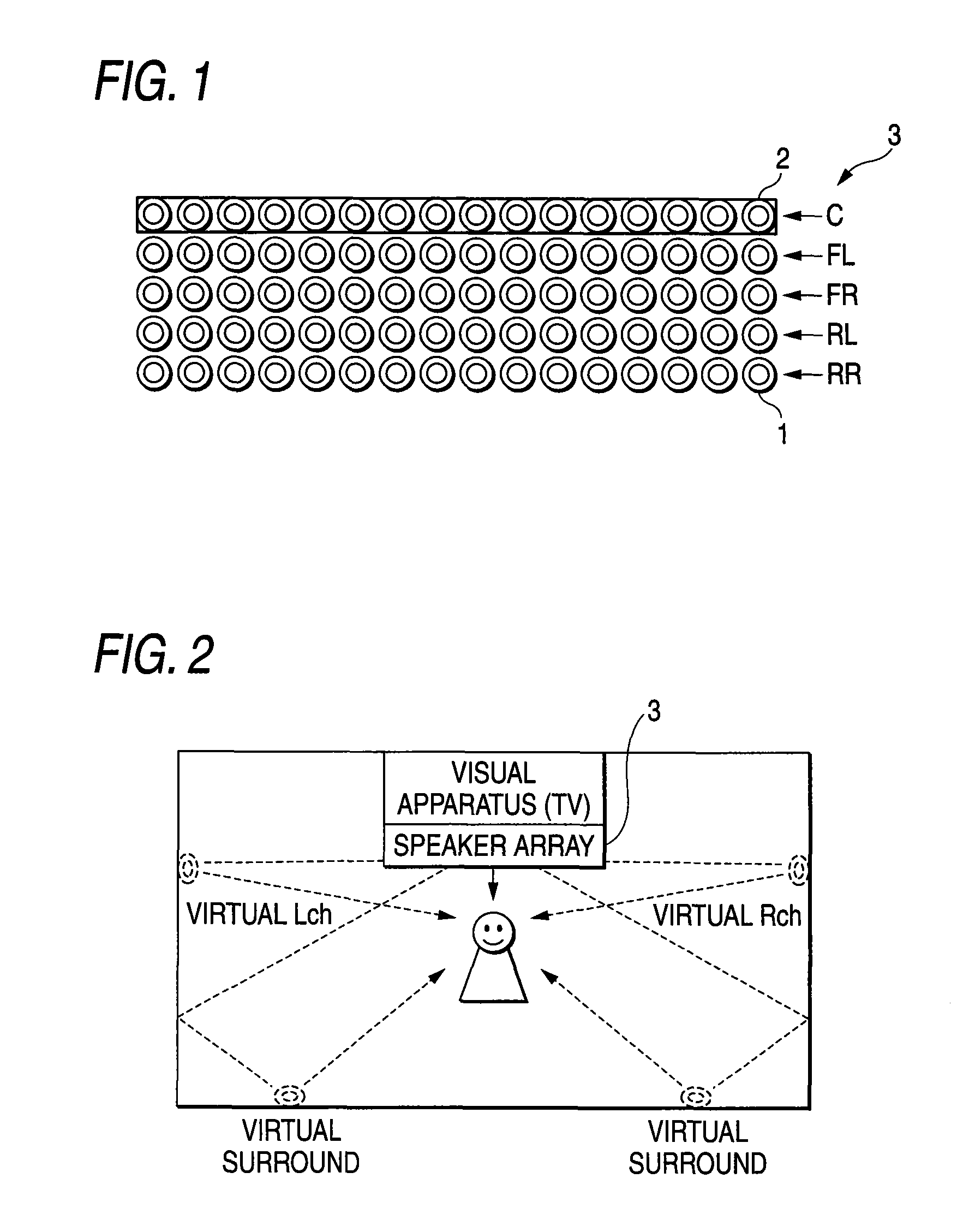
[0043]FIG. 1 is a diagram illustrating a loudspeaker apparatus in accordance with a first embodiment of the invention. The loudspeaker apparatus consists of a loudspeaker array 1 and an audio signal processing unit, but in this diagram the LOUDSPEAKER APPARATUS refers to the loudspeaker array 1 and a loudspeaker block assigned to the loudspeaker array 1 by the audio signal processing unit. The loudspeaker array 1 consists of 5-stage loudspeaker rows 2 (2-1, 2-2, 2-3, 2-4, and ...


PUM


Abstract

An array loudspeaker is constructed by stacking loudspeaker rows in a plurality of stages, each of the loudspeaker rows being formed by arranging loudspeaker elements in the form of a horizontal line. The loudspeaker rows are arranged in a zigzag form by, for example, offsetting the positions of the loudspeakers in the left and right direction for each stage. As for a high range signal, a two-stage portion of halves of the loudspeaker rows is used to narrow the pitch of the loudspeaker elements so as to prevent the grating lobe. As for a low range signal, the entire single-stage loudspeaker row is used to alleviate the deviation with respect to the directivity characteristics of the high range.

Description

[0001]This is a U.S. National Phase Application of PCT International Application PCT / JP2005 / 000159 filed on Jan. 4, 2005TECHNICAL FIELD[0002]The present invention relates to a loudspeaker apparatus for controlling the directivity of the audio signal by using a loudspeaker array in which a plurality of loudspeaker elements are arranged in an array form.BACKGROUND ART[0003]The technique for controlling the directivity of audio signal propagation by using a plurality of loudspeakers arranged in an array form has conventionally been proposed (e.g., patent document 1).[0004]FIG. 10 is a diagram explaining a basic principle of this technique. This diagram shows an example in which audio signals are outputted from a plurality of small loudspeakers arranged in a linear form, and control is provided such that the audio signals are directed toward a focal point F. Although the same audio signals are outputted from the respective loudspeakers, at that time a delay is provided to allow the audi...

Claims


Application Information

Patent Timeline
Patent Type & Authority Patents(United States)
IPC IPC(8): H04R5/02H04R5/00H04R3/00H04R1/40H03G5/00H04R3/12H04S3/00H04S5/02H04S7/00
CPCH04R1/403H04R3/12H04S3/00H04R2430/20H04R2205/022
Inventor KONAGAI, YUSUKETAMARU, TAKUYA
Owner YAMAHA CORP
Why Eureka
Try Eureka