System and method for providing adaptive voltage scaling with multiple clock domains inside a single voltage domain

a technology of adaptive voltage scaling and clock domain, applied in the field of low-power integrated circuits, can solve the problems of large power consumption of modern system-on-a-chip (soc) digital logic circuits, too large number of required adjustable voltage regulators (and associated external components), and the inability to achieve size-constrained portable devices. to achieve the effect of efficient provisioning of accurate adaptive voltage scaling

Active Publication Date: 2011-04-05
NAT SEMICON CORP
View PDF64 Cites 37 Cited by
  • Summary
  • Abstract
  • Description
  • Claims
  • Application Information

AI Technical Summary

Benefits of technology

[0023]To address the above-discussed deficiencies of the prior art, it is a primary object of the present invention to provide a system and method for efficientl...

Problems solved by technology

Modern System-on-a-Chip (SoC) digital logic circuits may consume large amounts of power both in terms of leakage power and dynamic power.
However, there are two main disadvantages with this approach.
First, the number of required adjustable voltage regulators (and associated external components) may be too large.
That ...

Method used


Image

  • System and method for providing adaptive voltage scaling with multiple clock domains inside a single voltage domain
  • System and method for providing adaptive voltage scaling with multiple clock domains inside a single voltage domain
  • System and method for providing adaptive voltage scaling with multiple clock domains inside a single voltage domain

Examples


embodiment 200

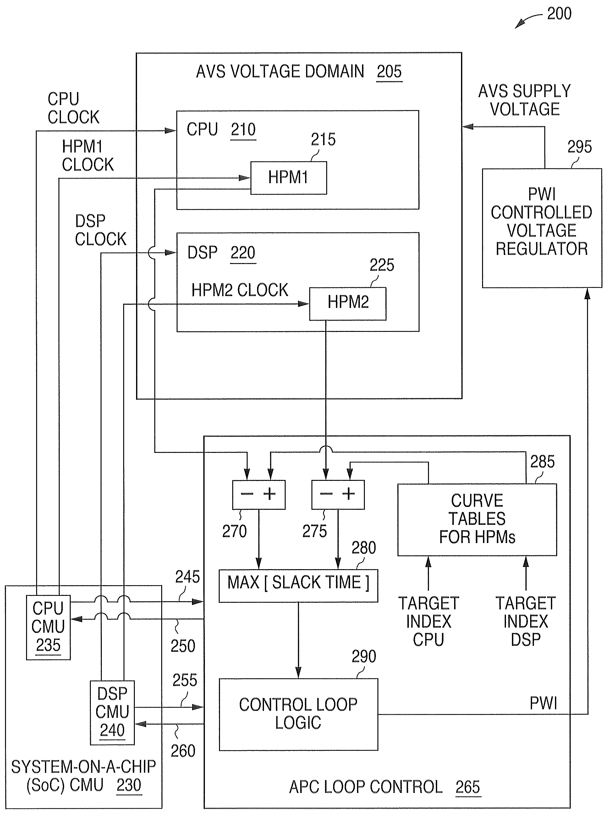
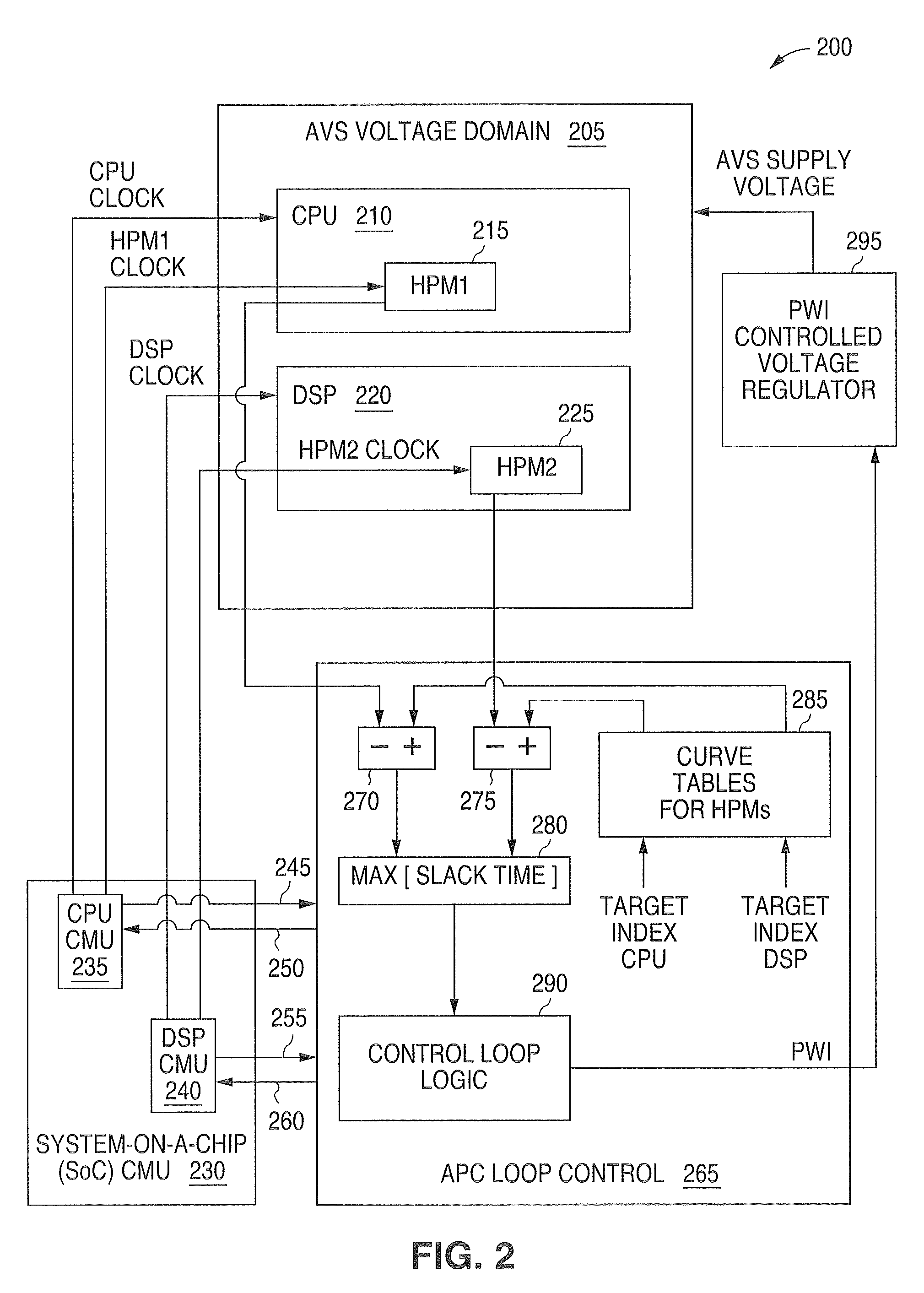
[0038]For an Adaptive Voltage Scaling (AVS) domain that is shared by more than one functional block, a system and method is needed to determine a supply voltage that is adequate for all of the functional blocks. FIG. 2 is a block diagram illustrating an advantageous embodiment 200 of the present invention that comprises two such functional blocks. The two functional blocks in the Adaptive Voltage Scaling (AVS) domain 205 of FIG. 2 are a central processing unit (CPU) 210 and a digital signal processing (DSP) unit 220. Each functional block comprises a separate clock domain. Although the principles of the present invention will be described with reference to two functional blocks, it is understood that the present invention is not limited to two functional blocks. It is understood that in the present invention any number of functional blocks may be implemented inside an Adaptive Voltage Scaling (AVS) domain.

[0039]The advantageous embodiment 200 of the present invention comprises a Sys...

embodiment 300

[0069]FIG. 3 is a block diagram illustrating an advantageous embodiment 300 of the present invention showing a portion of an Adaptive Voltage Scaling (AVS) system that comprises a plurality of independent functional blocks (310, 320, . . . , 330) in an adaptive voltage scaling (AVS) voltage domain 305. This embodiment comprises a plurality N of Hardware Performance Monitors (HPMs) (315, 325, . . . , 335).

[0070]As shown in FIG. 3, the first Hardware Performance Monitor (HPM1315) is associated with a CPU block 310. The second Hardware Performance Monitor (HPM2325) is associated with a DSP block 320. The last (or Nth) Hardware Performance Monitor (HPMN 335) is associated with an NTH block 330.

[0071]The first Hardware Performance Monitor (HPM1315) provides an output to a first subtraction unit 340. The first subtraction unit 340 also receives a value that represents the nominal expected output of the first Hardware Performance Monitor (HPM1315) from an HPM1 curve table (not shown in FIG...


PUM


Abstract

A system and method is disclosed for providing a plurality of hardware performance monitors for adaptive voltage scaling in an integrated circuit system that comprises a plurality of clock domains. Each hardware performance monitor is associated with one of the plurality of clock domains and provides a signal that measures a performance of its respective clock domain temperature, process corner and supply voltage. The difference between the measured performance and a nominal expected performance for each hardware performance monitor is determined. The largest of the plurality of difference signals is selected and used in an advanced power controller to provide adaptive voltage scaling for the integrated circuit system.

Description

CROSS REFERENCE TO RELATED APPLICATION[0001]The present invention is related to a United States Patent Application by the same inventors entitled “System and Method for Providing Hardware Performance Monitors for Adaptive Voltage Scaling With a Plurality of VT Logic Libraries” that was filed on Mar. 1, 2007 with patent application Ser. No. 11 / 712,709.TECHNICAL FIELD OF THE INVENTION[0002]The present invention relates generally to low power integrated circuits and, more particularly, to low power integrated circuits that employ adaptive voltage scaling and operate with a plurality of clock domains inside a single voltage domain.BACKGROUND OF THE INVENTION[0003]Modern digital integrated circuits such as central processing units (CPUs) are typically capable of operating with several different clock frequencies. Assume that a CPU can reduce its clock frequency while still meeting the processing requirements of an application that is running on the CPU. As is well known, a reduction in t...

Claims


Application Information

Patent Timeline
IPC IPC(8): G06F1/26G06F1/32
CPCG06F1/3296Y02B60/1285Y02D10/00
Inventor PENNANEN, JUHASALMI, PASI
Owner NAT SEMICON CORP
Why Eureka
Try Eureka