Fluid coupling
a technology of fluid passage and coupling, which is applied in the direction of water installations, thin material handling, construction, etc., can solve the problems of weak leg portion strength, valve shaft cannot be guided stably, and pressure loss, so as to reduce fluid passage resistance, reduce pressure loss, and reduce fluid passage resistance
- Summary
- Abstract
- Description
- Claims
- Application Information
AI Technical Summary
Benefits of technology
Problems solved by technology
Method used
Image
Examples
second embodiment
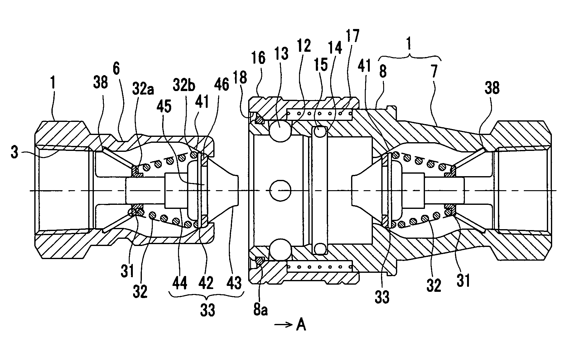
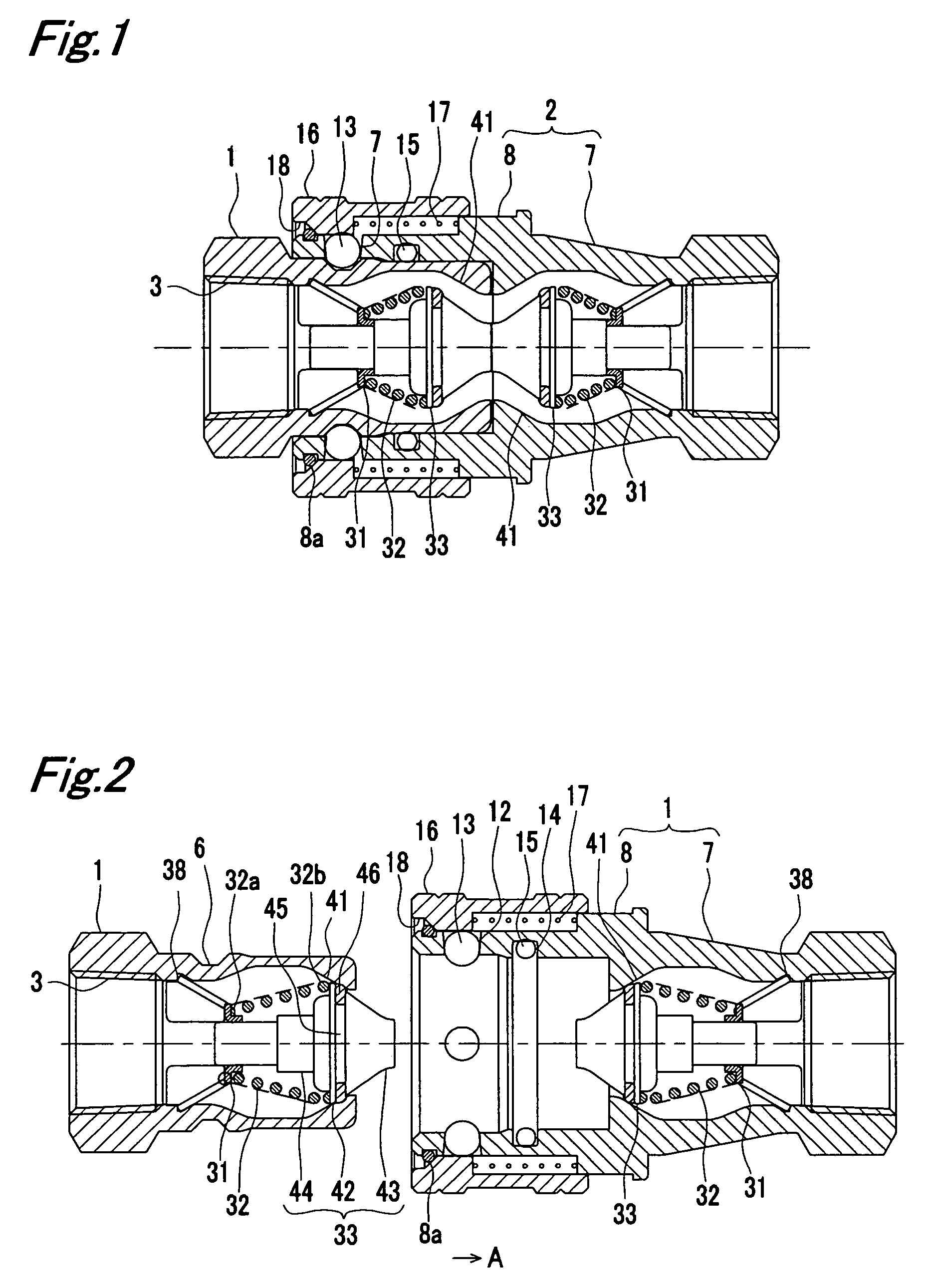
[0105]FIG. 9 shows the plug 1 and the socket 2 of the second embodiment. Like reference numerals are suffixed to the same components as in the first embodiment of FIG. 1 and description thereof is not repeated.
[0106]The plug 1 and the socket 2 have a conical cup 51 between the valve main body portion 42 of the valve 33 and the valve holder 31 and a spring 52 for urging the valve 33 is provided inside of the conical cup 51. The conical cup 51 constitutes the conical member of the present invention.
[0107]The conical cup 51 has a bottom wall 53 which makes contact with the top face of the valve holder 31 and the bottom wall 53 has an insertion hole 54 through which the valve shaft 44 of the valve 33 passes. The conical cup 51 has a peripheral wall 55 which is extended toward the valve main body portion 42 from the periphery edge of the bottom wall 53. As a valve holder, the valve holder 31 of the second modification shown in FIG. 6 is used.
[0108]The spring 52 is mounted in a compressed...
third embodiment
[0114]FIG. 13 shows the plug 1 and the socket 2 of the third embodiment. Like reference numerals are suffixed to the same components as the second embodiment of FIG. 9 and description thereof is not repeated.
[0115]The plug 1 and the socket 2 contain a bombshell type member 65 in which the streamlined valve holder 31 is provided integrally with the bottom wall 53 of the conical cup 51. This valve holder 31 contains a body 67 which supports the valve shaft 44 of the valve 33 passing through a hollow portion 66 therein and having a cap portion 64, and two pieces of supporting legs 68 which are extended from the body 67 so as to engage with the inner peripheral groove 38 to support the valve holder 31, the body 67 and the leg portions 68 being provided integrally. By forming the streamlined structure by providing the body 67 with the cap portion 64 integrally, no collision between the cap portion 64 and fluid is generated when fluid flows in, thereby securing a smooth entry of fluid. Fu...
fourth embodiment
[0118]FIG. 15 shows the plug 1 and the socket 2 of the fourth embodiment. Like reference numerals are suffixed to the same components as the second embodiment of FIG. 9 and description thereof is not repeated.
[0119]The valve 33, a valve supporting body 77 and a valve spring 78 are accommodated inside of the plug 1 and the main body portion 7 of the socket 2.
[0120]An end portion of the valve shaft 44 of the valve 33 on an opposite side to the valve main body portion 42 is formed in a semi-spherical shape. Formation into the semi-spherical shape blocks generation of collision between the valve shaft 44 and fluid when fluid enters, thereby securing a smooth flow-in of the fluid. Further, when fluid flows out, generation of the vortex is suppressed, so that fluid flows out with a small resistance.
[0121]The valve supporting body 77 constitutes a valve holder of the present invention. As shown in FIG. 15(c), the valve supporting body 77 is composed of an end winding portion 81 which makes...
PUM
 Abstract
Description
Claims
Application Information
 - R&D
- Intellectual Property
- Life Sciences
- Materials
- Tech Scout
- Unparalleled Data Quality
- Higher Quality Content
- 60% Fewer Hallucinations
Browse by: Latest US Patents, China's latest patents, Technical Efficacy Thesaurus, Application Domain, Technology Topic, Popular Technical Reports.
© 2025 PatSnap. All rights reserved.Legal|Privacy policy|Modern Slavery Act Transparency Statement|Sitemap|About US| Contact US: help@patsnap.com


