[0010]Other features and advantages of the present invention, as well as the invention itself, will be more fully understood from the following description of the various embodiments, when read together with the accompanying drawings, in which:
[0012]FIG. 2 is a flow chart depicting the types of size reduction equipment and the variety of size reduction procedures depending on the final carpet waste material form desired for the process equipment;
[0013]FIG. 3 depicts steps for coating the processed carpet waste material a bonding agent and subsequent forming process to produce the plastic composite product; and
[0013]FIG. 3 depicts steps for coating the processed carpet waste material a bonding agent and subsequent forming process to produce the plastic composite product; and
[0018]Unless otherwise noted, the use of one material when describing a particular application, process, or embodiment does not limit the described application, process, or embodiment to the specific material identified. The materials may be used interchangeably, in accordance with the described teachings herein. Moreover, the terms “PCs,”“composite sheets,” and the like, are used interchangeably herein to describe plastic composite boards or sheets made from recycled carpet waste which may include additional additives. In addition to PCs, other composite products may be manufactured utilizing, in whole or in part, recycled carpet waste. A non-limiting list of such composite products include plastic piping, molded articles such as flower pots or seeding trays, building siding or roofing, fencing, furniture, or other types of extruded, injection molded, and / or compression molded products.
[0025]As an optional step, the granules or pulverized particles may be fiberized. The fiberizing process includes a mechanical roughing of the surface so that the surface takes on a fuzz-like characteristic that may be desirable for the composite product process described below. After processing to the desired condition, the material is then sent to the composite production process.
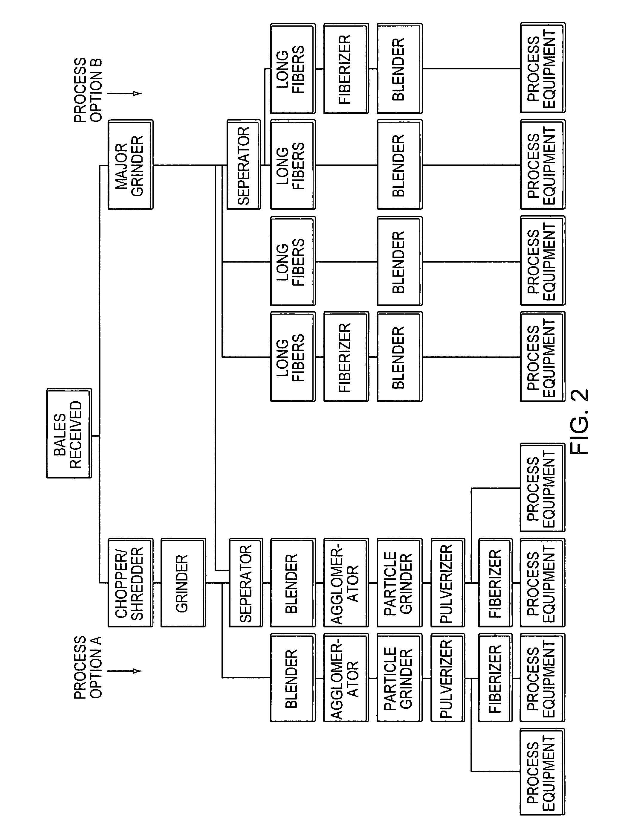
[0019]FIG. 2 shows the types of equipment and the variety of procedures for carpet waste size reduction, depending on the final form desired for the process equipment. The final form may also be dependent on the desired finished composite product and physical or visual appearance properties. In short, the carpet waste is processed as described below to reduce its size. Then the size-reduced carpet waste is mixed or coated with a binder to produce material that is subjected to temperature and / or pressure to yield composite material. The size reduction process may take place at the same facility where the PCs are manufactured, or the carpet waste may be processed at a first facility and delivered to a second facility for incorporation into the PC products. Post-manufacture treatments for the composite material are also described below.
[0025]As an optional step, the granules or pulverized particles may be fiberized. The fiberizing process includes a mechanical roughing of the surface so that the surface takes on a fuzz-like characteristic that may be desirable for the composite product process described below. After processing to the desired condition, the material is then sent to the composite production process.
[0020]The carpet waste is made up of selvedge, post-industrial carpet waste, post-consumer carpet waste, or waste carpet reclaimed from landfills. Post-industrial carpet waste refers generally to waste material produced as a byproduct to the manufacturing process, such as trimmed carpet segments, as well as to carpet that fails to pass quality or other inspections, thus rendering it unsuitable for consumer use. Post-consumer carpet waste refers generally to carpet waste that is generated during installation at a consumer site or that is removed from a consumer site during demolition and / or replacement. Regardless, the terms selvedge, carpet waste, waste carpet, reclaimed waste, recycled waste, and similar terms are used herein interchangeably and may be used in the processes described herein interchangeably. These materials generally will be in baled form to begin the size reduction phase of the pre-processing. The bales vary in size but usually are about 1000 lb. to about 2000 lb. All of the equipment described in the carpet reduction processes below may be supplied by Pallmann Maschinenfabrik GMBH, of other manufacturers that produce similar equipment. Alternative manufacturers of specific equipment are identified below.
[0021]The first step in the size reduction phase includes reducing the waste to a manageable size for the remainder of the process. As depicted in FIG. 2, either a combination of a shredder / chopper and grinder (Process Option A), or a major capacity grinder (Process Option B) is used to process the materials to smaller sizes. Process Option A may be used to reduce carpet waste to pellets or granules that may be further processed into various PC products. The shredder / chopper first reduces the selvedge or carpet waste to chunks approximately three inches square (3″×3″), although other sizes are contemplated, depending on the equipment used. In addition to Pallmann Maschinenfabrik, the shredder / chopper may be manufactured by Vecoplan, LLC, or Weima America, Inc. The shredded material then passes through a grinder which further reduces the chunks to a fiber fluff material with a diameter of the fibers similar to the diameter of the original carpet fibers and a length of about 0.25″ to about 1″. Other manufactures of comparable grinders include Vecoplan, LLC, Cumberland Engineering Corp., and Republic Machine, Inc.
[0022]The waste optionally can be run through a separator which acts as a hammer mill / cyclone to remove the dirt from the carpet waste. In this step, some of the carpet backing containing inorganic fillers may also be removed. Generally, however, it is unnecessary to deliberately separate the various carpet components prior to incorporating the recycled carpet waste into PCs. All of the components of carpet may be used, not only one component, such as the carpet fibers, as certain known methods disclose. Thus, manufacturing time is decreased, since the step of component separation is not utilized. The slightly-size reduced material, due to the hammer mill effect, is ready for the next step, the agglomeration process, while the dirt and carpet backing materials that may have been removed from the small chunks are disposed. Carpet backing that is not removed, however, does not have any adverse effect when incorporated into a PC using recycled carpet waste. The fiber fluff, regardless of the use of the separator or not, also may be blended with other materials such as wood or natural fibers, synthetic fibers (i.e., fiberglass), inorganic fillers, or other reinforcing fillers. The fiber fluff material or the blended material is then conveyed to the agglomeration step.
[0027]Significantly, it has been determined that it is not necessary to separate or classify the various materials contained in selvedge or carpet waste, even though most carpet surface materials are nylons, polyester, polypropylene, or wool and the backing material is usually polypropylene and / or highly filled synthetic latex. These materials exhibit considerably different physical properties and processing properties, but the entire waste product may be used in the composite sheet material, regardless of the differences in the components that comprise the carpet waste. The waste carpet, having been made into an agglomerate, a fiberized agglomerate, a pulverized agglomerate, a fiberized, pulverized agglomerate, a fiberized fluff, etc., becomes the base material for the composite product. Additionally, other waste fiber or fiberized waste fiber may also be used to manufacture a composite product. The whole range of materials in carpet waste may be part of the composition.
[0023]The agglomeration of the above materials occurs inside the agglomerator. The materials enter a horizontal drum containing a revolving rotor that is shaped so as to force the fiber fluff or blends against the drum wall. The drum wall is perforated so that, as the rotor forces the contained materials against the perforated wall, the material is forced through the perforations, thereby forming strands of a fixed diameter. On the outside of the drum are stationary knives which cut the strands into a fixed length. During this process, the material is heated by friction to a temperature that remains below the melting point of the highest melting point material in the blend. The temperature is controlled by the speed of the rotor, the diameter of the perforations, and the thickness of the drum wall. As each component of the carpet waste, i.e., backing and carpet fibers, is pressed against the wall of the drum, that material heats up due to friction, until the material sufficiently softens, such that it is then pressed through the perforated drum by the rotor. The agglomerating machinery could be replaced by a pellet mill manufactured by Bliss Industries or California Pellet Mill Co.
[0024]The granules that are formed in the agglomeration step are generally cylindrical in shape and approximately 0.125″ in diameter and about 0.125″ to about 0.25″ long. The diameter and length of the granules can be modified by changing the diameter of the holes in the drum wall and / or changing the speed of the rotation against the knives. Because the granules are hot when they are formed and cut to length, some of the granules may be stuck to one another. Therefore, for better size consistency, the granules next pass through a grinder which separates any stuck granules. This grinder step may also be used to reduce the size of the granules, and / or the granules may be further reduced in size by a pulverizer. For example, if the final desired dimension is less than 0.125″, the pulverizer may be used to reduce the particle size to 8-16 mesh. This is the equivalent of about 0.04″ to about 0.10″.
[0024]The granules that are formed in the agglomeration step are generally cylindrical in shape and approximately 0.125″ in diameter and about 0.125″ to about 0.25″ long. The diameter and length of the granules can be modified by changing the diameter of the holes in the drum wall and / or changing the speed of the rotation against the knives. Because the granules are hot when they are formed and cut to length, some of the granules may be stuck to one another. Therefore, for better size consistency, the granules next pass through a grinder which separates any stuck granules. This grinder step may also be used to reduce the size of the granules, and / or the granules may be further reduced in size by a pulverizer. For example, if the final desired dimension is less than 0.125″, the pulverizer may be used to reduce the particle size to 8-16 mesh. This is the equivalent of about 0.04″ to about 0.10″.
[0025]As an optional step, the granules or pulverized particles may be fiberized. The fiberizing process includes a mechanical roughing of the surface so that the surface takes on a fuzz-like characteristic that may be desirable for the composite product process described below. After processing to the desired condition, the material is then sent to the composite production process.
[0021]The first step in the size reduction phase includes reducing the waste to a manageable size for the remainder of the process. As depicted in FIG. 2, either a combination of a shredder / chopper and grinder (Process Option A), or a major capacity grinder (Process Option B) is used to process the materials to smaller sizes. Process Option A may be used to reduce carpet waste to pellets or granules that may be further processed into various PC products. The shredder / chopper first reduces the selvedge or carpet waste to chunks approximately three inches square (3″×3″), although other sizes are contemplated, depending on the equipment used. In addition to Pallmann Maschinenfabrik, the shredder / chopper may be manufactured by Vecoplan, LLC, or Weima America, Inc. The shredded material then passes through a grinder which further reduces the chunks to a fiber fluff material with a diameter of the fibers similar to the diameter of the original carpet fibers and a length of about 0.25″ to about 1″. Other manufactures of comparable grinders include Vecoplan, LLC, Cumberland Engineering Corp., and Republic Machine, Inc.
[0025]As an optional step, the granules or pulverized particles may be fiberized. The fiberizing process includes a mechanical roughing of the surface so that the surface takes on a fuzz-like characteristic that may be desirable for the composite product process described below. After processing to the desired condition, the material is then sent to the composite production process.
[0027]Significantly, it has been determined that it is not necessary to separate or classify the various materials contained in selvedge or carpet waste, even though most carpet surface materials are nylons, polyester, polypropylene, or wool and the backing material is usually polypropylene and / or highly filled synthetic latex. These materials exhibit considerably different physical properties and processing properties, but the entire waste product may be used in the composite sheet material, regardless of the differences in the components that comprise the carpet waste. The waste carpet, having been made into an agglomerate, a fiberized agglomerate, a pulverized agglomerate, a fiberized, pulverized agglomerate, a fiberized fluff, etc., becomes the base material for the composite product. Additionally, other waste fiber or fiberized waste fiber may also be used to manufacture a composite product. The whole range of materials in carpet waste may be part of the composition.
[0027]Significantly, it has been determined that it is not necessary to separate or classify the various materials contained in selvedge or carpet waste, even though most carpet surface materials are nylons, polyester, polypropylene, or wool and the backing material is usually polypropylene and / or highly filled synthetic latex. These materials exhibit considerably different physical properties and processing properties, but the entire waste product may be used in the composite sheet material, regardless of the differences in the components that comprise the carpet waste. The waste carpet, having been made into an agglomerate, a fiberized agglomerate, a pulverized agglomerate, a fiberized, pulverized agglomerate, a fiberized fluff, etc., becomes the base material for the composite product. Additionally, other waste fiber or fiberized waste fiber may also be used to manufacture a composite product. The whole range of materials in carpet waste may be part of the composition.
[0027]Significantly, it has been determined that it is not necessary to separate or classify the various materials contained in selvedge or carpet waste, even though most carpet surface materials are nylons, polyester, polypropylene, or wool and the backing material is usually polypropylene and / or highly filled synthetic latex. These materials exhibit considerably different physical properties and processing properties, but the entire waste product may be used in the composite sheet material, regardless of the differences in the components that comprise the carpet waste. The waste carpet, having been made into an agglomerate, a fiberized agglomerate, a pulverized agglomerate, a fiberized, pulverized agglomerate, a fiberized fluff, etc., becomes the base material for the composite product. Additionally, other waste fiber or fiberized waste fiber may also be used to manufacture a composite product. The whole range of materials in carpet waste may be part of the composition.
[0027]Significantly, it has been determined that it is not necessary to separate or classify the various materials contained in selvedge or carpet waste, even though most carpet surface materials are nylons, polyester, polypropylene, or wool and the backing material is usually polypropylene and / or highly filled synthetic latex. These materials exhibit considerably different physical properties and processing properties, but the entire waste product may be used in the composite sheet material, regardless of the differences in the components that comprise the carpet waste. The waste carpet, having been made into an agglomerate, a fiberized agglomerate, a pulverized agglomerate, a fiberized, pulverized agglomerate, a fiberized fluff, etc., becomes the base material for the composite product. Additionally, other waste fiber or fiberized waste fiber may also be used to manufacture a composite product. The whole range of materials in carpet waste may be part of the composition.
[0035]Table B presents the ranges of various components that may be utilized in composite formulations to produce acceptable PCs. Specifically, materials utilized may include colorants, wood filler, fire retardants, fiberglass, mold inhibitors, binders, and recycled carpet waste. The recycled carpet waste can be about 20% to about 98% of the total formula weight and still retain acceptable physical properties in the composite sheet. Certain embodiments may include carpet wastes in the amount of about 90% to about 98% total weight. Still other embodiments may include carpet wastes in the amount of about 94% to about 95% total weight. It has been found that composites that utilize approximately 95% carpet waste and about 5% binding agent produce a composite that exhibits satisfactory performance while being economically advantageous, due to the low cost associated with using recycled carpet waste versus virgin materials. In other embodiments, a 9:1 ratio of carpet waste to MDI, up to a 49:1 ratio of carpet waste to MDI may be utilized. Table B also presents percentages of additives, such as wood filler, color, fire retardant, fiberglass, and mold inhibitor that may be added to the binder / carpet waste mixture. The percentages of these additives may be up to those identified in Table B, relative to the carpet waste / MDI content. Additionally, there is no discernible difference in the performance of the composite when using recycled carpet waste obtained from post-industrial carpet waste or post-consumer carpet waste, as compared with using virgin materials.
[0018]Unless otherwise noted, the use of one material when describing a particular application, process, or embodiment does not limit the described application, process, or embodiment to the specific material identified. The materials may be used interchangeably, in accordance with the described teachings herein. Moreover, the terms “PCs,”“composite sheets,” and the like, are used interchangeably herein to describe plastic composite boards or sheets made from recycled carpet waste which may include additional additives. In addition to PCs, other composite products may be manufactured utilizing, in whole or in part, recycled carpet waste. A non-limiting list of such composite products include plastic piping, molded articles such as flower pots or seeding trays, building siding or roofing, fencing, furniture, or other types of extruded, injection molded, and / or compression molded products.
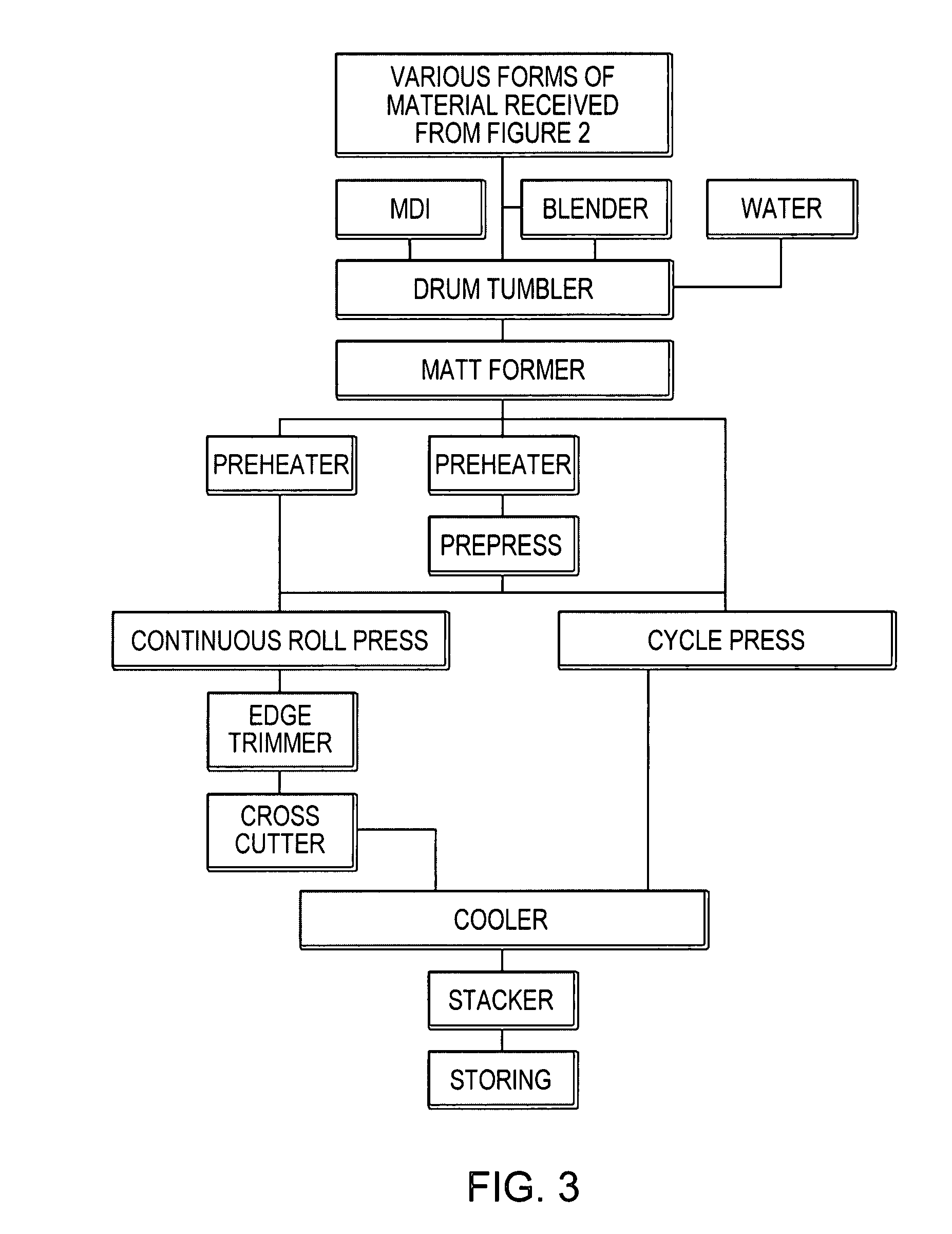
[0028]After the size reduction process(es), the carpet waste is ready to be formed into composite sheets, a process for which is depicted in FIG. 3. The carpet waste materials may be loaded into a large rotating drum or a drum with rotating mixing blades and / or a resination blow line. This equipment is used to coat the carpet waste with a binding agent. Other materials such as natural fiber fillers or inorganic fillers may be loaded with the carpet waste material. If the material is loaded into a drum, water and / or a binding agent (such as MDI) are sprayed out of the resination blow line to coat the materials, while the drum and / or blades spin to cause the material within to become evenly distributed. The addition of water may achieve a desired moisture content for the material and prepare the material for the binding agent. For the resination blow line method, the material is blown through a tube that has water and MDI introduced into it. The blowing action causes the air to become turbulent which allows the water and MDI to evenly coat the material. In one embodiment, the binding agent is applied in this manner to the granules or fibers at a concentration of about 1% to about 20% of the total weight of the granules plus any other additives. Concentrations between about 2% to about 10% and about 5% to about 6% are also contemplated. Generally, higher concentrations of resin produce composite sheets with higher moduli of elasticity and rupture. This coated carpet waste dries rapidly under ambient conditions, allowing the granules or fibers to continue to flow without adhering to one another. Accordingly, once coated and dried, the resin coated particles need not be used immediately, and may be stored and / or transported for later use.
[0033]Heat is generally delivered to the platens in the form of hot water, steam, electric coils, or circulating heated chemicals. In certain embodiments of the process, the platens may be heated from about 100° F. to about 600° F. Temperature ranges from about 200° F. to about 550° F., and about 340° F. to about 420° F. also may be desirable. Additionally, temperature ranges from about 420° F. to about 550° F. may be utilized. Final internal temperatures of the composite being compressed within the cycle press will be dependent at least in part on the temperature of the platens and compression time. If left in the cycle press for a sufficient period of time, the internal temperatures of the composite material will generally equal those of the platens, the ranges of which are given above. Final internal temperatures up to about 250° F., about 300° F., about 340° F., about 350° F., about 400° F., about 420° F., and about 480° F. have produced composite sheets displaying acceptable performance. Unlike known recycled carpet waste composite sheet material manufacturing processes, which heat the composite sheets to a temperature below the melting points of the carpet fibers and other carpet components, it has been discovered that heating the carpet waste to higher temperatures may be desirable. For example, temperatures of approximately 340° F. will melt polypropylene, a component in many modern carpet constructions, without melting any nylon fibers (that melt at about 420° F.). The melted polypropylene, combined with binding agent resins of the types disclosed herein, form a sheet material having very desirable properties. The unmelted nylon provides additional structural strength to the finished composite and may increase flexural strength, though completely melting the carpet fibers can also produce a PC displaying acceptable performance properties. Pressures applied by the platens in the heating press may range from about 150 psi to about 6000 psi or greater, to obtain a the desired thickness and density.
[0046]According to an alternative embodiment, the PC may be manufactured using a continuous roll process. The continuous roll press is a double belted press capable of maintaining a range of temperatures and pressures on the mat to allow the binding agent reaction and melting of select components to take place. The continuous roll press belts may be steel or other material. Process parameters for a continuous roll press are depicted in Table A-2. Temperatures utilized are generally similar to those utilized in the cycle press process.
[0046]According to an alternative embodiment, the PC may be manufactured using a continuous roll process. The continuous roll press is a double belted press capable of maintaining a range of temperatures and pressures on the mat to allow the binding agent reaction and melting of select components to take place. The continuous roll press belts may be steel or other material. Process parameters for a continuous roll press are depicted in Table A-2. Temperatures utilized are generally similar to those utilized in the cycle press process.
[0031]In one embodiment, composite sheets are manufactured using a cycle press, which may have single or multi-daylight openings. Ranges of various process parameters for manufacturing various embodiments of PCs utilizing recycled carpet waste in a cycle press are presented in Table A-1, below. The composite material is transferred into the cycle press where it is subjected to temperature and pressure from a top and bottom platen that compresses the mat to a predetermined thickness or height. The elevated temperature and pressure activates the binding agent and, depending on the temperature, melts certain of the carpet components while leaving others unmelted, to produce in a finished board or sheet. During the cycle press process, steam may be injected into the mat to ensure thorough heating of the binding agent and bonding of the composite material. The cycle press may also use an active cooling cycle to reduce the temperature of the board before it exits the press. The platens may be engraved with a pattern to give the board outer surface a structured pattern.
[0046]According to an alternative embodiment, the PC may be manufactured using a continuous roll process. The continuous roll press is a double belted press capable of maintaining a range of temperatures and pressures on the mat to allow the binding agent reaction and melting of select components to take place. The continuous roll press belts may be steel or other material. Process parameters for a continuous roll press are depicted in Table A-2. Temperatures utilized are generally similar to those utilized in the cycle press process.
[0048]For example, pressures from about 150 psi to about 6000 psi are used to squeeze the fiber mat to the desired thickness and density of the final product. The continuous roll press consists of a press structure that tensions the belts. In general, the press includes a number of frame units, depending on the length of the press and pressure that is required for a particular application. Cylinders arranged at the frame units in various combinations exert the desired pressure. The press includes top and bottom heated platens which roller rods and the belts travel over. The press has an infeed head to guide the roller rods, belts and mat to be pressed. The roller rods are located between the heated platens and the belts and support the mat as it is moved from one cylinder to the next. The belts are driven by two or more drums at generally opposite ends of the roll press. Drum scrapers may be used to keep the board from sticking to the belts. A release agent also may be sprayed onto the belts to keep the mat from sticking to the belts, allowing the composite to exit easily the press at the completion of forming. A control system regulates the operation of the press, such as the speed of the belts, temperature, pressure, thickness of the mat, etc.
[0049]The continuous roll press transfers heat to the binding agent-coated composite material. As the heat activates the coating, the cylinders press the mat together to achieve the desired thickness. Thus, while the mat material moves from the infeed section of the press, the mat's thickness is reduced while being heated to a temperature that ensures activation of the binding agent and melting of certain fibers. As the mat moves through the continuous roll press, the platens gradually reduce the thickness of the mat to a predetermined thickness. Depending on the amount of material introduced to the infeed section of the press, the density of the finished board is directly related to its final thickness.
[0046]According to an alternative embodiment, the PC may be manufactured using a continuous roll process. The continuous roll press is a double belted press capable of maintaining a range of temperatures and pressures on the mat to allow the binding agent reaction and melting of select components to take place. The continuous roll press belts may be steel or other material. Process parameters for a continuous roll press are depicted in Table A-2. Temperatures utilized are generally similar to those utilized in the cycle press process.
[0049]The continuous roll press transfers heat to the binding agent-coated composite material. As the heat activates the coating, the cylinders press the mat together to achieve the desired thickness. Thus, while the mat material moves from the infeed section of the press, the mat's thickness is reduced while being heated to a temperature that ensures activation of the binding agent and melting of certain fibers. As the mat moves through the continuous roll press, the platens gradually reduce the thickness of the mat to a predetermined thickness. Depending on the amount of material introduced to the infeed section of the press, the density of the finished board is directly related to its final thickness.
[0050]After the binding of the material and desired height dimension of the mat has been reached in a continuous roll press, a board is formed which is in the shape of a continuous ribbon. When the ribbon exits the press, it undergoes a continuous edge trimming operation to reach the desired width and then it is cross-cut to a pre-selected length. The ribbon is transported through the trimming and cross-cutting operations by a roller conveyor and pinch rollers. The cut boards are then transported to a cooling station. The cooling station can employ a variety of different machines such as a star cooler, with subsequent stacking, or a stacking roller conveyor. The star cooler is a large diameter wheel with multiple rows of spoked arms extending from the wheel. The arms lift each board from the conveyor and allow the boards to rotate with the wheel and be air cooled. If needed, the continuous roll press can have a cooling section with chilled rollers near the press outlet. This will cool the board (as described above) eliminating the need for further cooling. The board is then conveyed to a stacking operation and stored for future use. Alternatively the boards may be conveyed to a separate cooling press as described above. The boards are now ready to be shipped or they can go through a variety of decorating alternatives.
[0057]Another laminating technique used with the composite product is foil laminating. This technique can be referred to as wrapping; wherein, the composite product profile is wrapped in the decorative foil. After the composite product profile has been sanded, the profile passes through a wrapping device that takes the foil wrap from a coil then applies the adhesive (and primer, if required) to the foil. In a continuous process, the foil wrap is then passed over the composite product profile. Using a series of rollers, the foil wrap is shaped to the composite product profile. The foil wrap may incorporate an integral topcoat material, such as polyurethane, acrylic, or other protective materials, for physical property enhancement. If, however, the foil wrap integrates only the decorative elements, then the wrapped composite product will require a separate topcoat for certain applications.
[0053]The composite product may be embossed after manufacturing. The embossing is accomplished with an embossing plate or roll. The plate or roll has the pattern to be transferred to the product on the surface of the plate or roll. This surface is heated to a temperature that will soften the surface of the composite product. Then the plate or roll is pressed onto the surface of the product to give the desired pattern transfer. As the surface of the composite product cools, the embossed pattern becomes fixed on the surface of the composite product. The embossed composite product is now ready to be coated, or if no coating is required for the end-use product, it is ready for packaging.
[0051]FIG. 4 shows the finishing and decorating steps that may be employed following cutting to final width. The composite product can now be processed further to change the cross-sectional profile to take on the shape required in the finished product. The processing can be done on a variety of cutting machines of different designs, the most common of which is a molder using rotating knives. This machine allows for the setting of the knife blades to adjust the cut to the desired profile. Another common device is the router which cuts a specific groove or grooves (routs) into the surface of the composite product. The router has the same effect as the molder in that it changes the initial profile out of the process into the desired profile required for the final product.
[0052]The profile may also be changed using thermoforming methods. In this case, the composite product is placed in a mold of the desired profile and with heat and pressure the product takes on the shape of the mold. This profile change offers an additional decorating capability in that the desired color and / or pattern may be on a transfer foil placed in the mold. With the application of the heat and pressure during the process, the color and / or pattern are transferred from the carrier foil to the composite product. Thus, at the end of the thermoforming process, the composite product has the desired profile and also the desired decoration.
[0053]The composite product may be embossed after manufacturing. The embossing is accomplished with an embossing plate or roll. The plate or roll has the pattern to be transferred to the product on the surface of the plate or roll. This surface is heated to a temperature that will soften the surface of the composite product. Then the plate or roll is pressed onto the surface of the product to give the desired pattern transfer. As the surface of the composite product cools, the embossed pattern becomes fixed on the surface of the composite product. The embossed composite product is now ready to be coated, or if no coating is required for the end-use product, it is ready for packaging.
[0055]The composite product also may be decorated using transfer foils. Once again the product is first sanded to smooth the surface, then an adhesive layer is applied to the profile using a conventional application technique. The transfer foil has the desired color and / or pattern on a polymeric substrate, and is brought into contact with the surface of the product using stamping equipment designed for the specific application. Using heat and pressure, the color and / or pattern is transferred from the foil to the product. The heat required for the transfer activates an adhesive layer on the surface of the profile ensuring bonding of the decoration to the profile. With the color and / or pattern now on the composite product, the spent foil is then collected for disposal, and the finished product has the desired decorated effect.
[0056]Another decorating method that may be employed is lamination. Several materials may be used as the laminate surface, such as wood veneers, synthetic veneers, foils, films, and polymeric sheets. The application of rigid laminates like wood veneers is done using conventional laminating equipment. Generally, an adhesive system (either a wet adhesive system or a hot-melt adhesive system) employing a primer and an adhesive is applied to the PC substrate. The rigid surface laminate is then applied to the substrate and temperature and pressure are applied. After the temperature-pressure step, the laminated product is then set for a fixed period of time to allow the adhesive system to cure. In the case of the composite product, the composite product is the substrate. The adhesive system, usually a hot-melt adhesive, is applied to the composite product. The rigid veneer is then placed on the adhesive layer forming a sandwich of composite product, adhesive, and rigid laminate. The sandwich is then pressed to secure the bond of the laminate to the composite product. After curing the laminated product with the desired decorative appearance is ready for packaging.
[0054]Composite products that will be decorated first pass through a sander. This smoothing of the surface prepares the product for coating, transfers, and laminating. The sanded or embossed composite product may be coated with primers, finish paints, or stains. The coating application employs various conventional spray techniques using exhaust systems to remove the excess spray and solvents. Either penetrating or film-forming coatings may also be applied, and the choice is dependent on the desired finished product appearance and application. The sanded composite product can also act as a core to which decorative and protective layer(s) may be hot stamped from a foil or film or laminated to achieve improved physical and visual enhancement. In this regard, U.S. patent application Ser. No. 11 / 054,258, filed Feb. 9, 2005, and published as U.S. Patent Application Publication No. 2006 / 0147693, and U.S. Provisional Patent Application Ser. No. 60 / 641,308, filed Jan. 4, 2005, describe exemplary processes and are incorporated by reference herein in their entireties.
[0055]The composite product also may be decorated using transfer foils. Once again the product is first sanded to smooth the surface, then an adhesive layer is applied to the profile using a conventional application technique. The transfer foil has the desired color and / or pattern on a polymeric substrate, and is brought into contact with the surface of the product using stamping equipment designed for the specific application. Using heat and pressure, the color and / or pattern is transferred from the foil to the product. The heat required for the transfer activates an adhesive layer on the surface of the profile ensuring bonding of the decoration to the profile. With the color and / or pattern now on the composite product, the spent foil is then collected for disposal, and the finished product has the desired decorated effect.
[0057]Another laminating technique used with the composite product is foil laminating. This technique can be referred to as wrapping; wherein, the composite product profile is wrapped in the decorative foil. After the composite product profile has been sanded, the profile passes through a wrapping device that takes the foil wrap from a coil then applies the adhesive (and primer, if required) to the foil. In a continuous process, the foil wrap is then passed over the composite product profile. Using a series of rollers, the foil wrap is shaped to the composite product profile. The foil wrap may incorporate an integral topcoat material, such as polyurethane, acrylic, or other protective materials, for physical property enhancement. If, however, the foil wrap integrates only the decorative elements, then the wrapped composite product will require a separate topcoat for certain applications.
[0057]Another laminating technique used with the composite product is foil laminating. This technique can be referred to as wrapping; wherein, the composite product profile is wrapped in the decorative foil. After the composite product profile has been sanded, the profile passes through a wrapping device that takes the foil wrap from a coil then applies the adhesive (and primer, if required) to the foil. In a continuous process, the foil wrap is then passed over the composite product profile. Using a series of rollers, the foil wrap is shaped to the composite product profile. The foil wrap may incorporate an integral topcoat material, such as polyurethane, acrylic, or other protective materials, for physical property enhancement. If, however, the foil wrap integrates only the decorative elements, then the wrapped composite product will require a separate topcoat for certain applications.
[0057]Another laminating technique used with the composite product is foil laminating. This technique can be referred to as wrapping; wherein, the composite product profile is wrapped in the decorative foil. After the composite product profile has been sanded, the profile passes through a wrapping device that takes the foil wrap from a coil then applies the adhesive (and primer, if required) to the foil. In a continuous process, the foil wrap is then passed over the composite product profile. Using a series of rollers, the foil wrap is shaped to the composite product profile. The foil wrap may incorporate an integral topcoat material, such as polyurethane, acrylic, or other protective materials, for physical property enhancement. If, however, the foil wrap integrates only the decorative elements, then the wrapped composite product will require a separate topcoat for certain applications.
[0058]If the end-use product application requires significant surface property enhancements, such as abrasion resistance, a topcoat may be added to the decorating process. The topcoat can be polyurethane, acrylic, or other protective material that will impart better physical properties to the surface of the wrapped finished product. The topcoat may be spray applied or hot melt applied. If spray applied, the wrapped composite product will pass through a spray applicator and then may or may not pass through a curing device, such as an ultra-violet radiation station. If the topcoat is hot melt applied, then a layer of polyurethane is applied to flat surfaces of the decorated composite product. The cure process for this type of material is time dependent and could take several days depending on the hot melt topcoat chosen for a specific end-use application for the completed finished product.
[0059]A number of embodiments of the invention have been described. Nevertheless, it will be understood that various modifications may be made without departing from the spirit and scope of the invention. Accordingly, other embodiments are within the scope of the following claims.

