IP multicast in VLAN environment

a multicast and vlan technology, applied in the field of communication networks, can solve the problems of waste of bandwidth in the distribution of multicast packets, adds to the complexity of layer 3 switches,

Active Publication Date: 2011-04-12
AVAYA TECH CORP +1
View PDF22 Cites 286 Cited by
  • Summary
  • Abstract
  • Description
  • Claims
  • Application Information

AI Technical Summary

Benefits of technology

[0028]In some embodiments the switch includes a layer-3 routing unit which routes at least some IP multicast routing related packets between ports of the same VLAN. In some embodiments, the multicast detector prevents the layer-2 bridging of packets, irrespective of the IP destination address of the packets, of the MAC destination address of the packets and / or of subscription information of hosts directly connected to the switch.

Problems solved by technology

This adds to the complexity of layer-3 switches.
This distribution of multicast packets is very wasteful in bandwidth.

Method used


Image

  • IP multicast in VLAN environment
  • IP multicast in VLAN environment
  • IP multicast in VLAN environment

Examples


Embodiment Construction

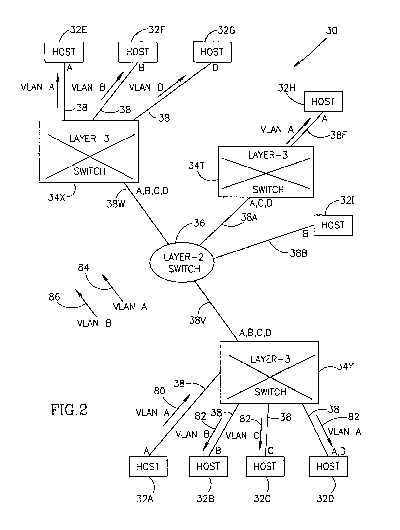
[0041]FIG. 2 is a schematic block diagram of a local area network 30 illustrating the distribution of IP multicast packets, in accordance with an embodiment of the present invention. Network 30 comprises a plurality of hosts 32 (labeled 32A, 32B, 32C, etc.) and layer-3 switches 34 (labeled 34X, 34Y and 34T). Network 30 may also comprise one or more layer-2 switches 36 which do not perform layer-3 routing. Switches 34 and 36 and hosts 32 are connected through links 38. Each link 38 is marked in FIG. 2 with letters (A, B, C and / or D) which designate the VLANs supported by the link.

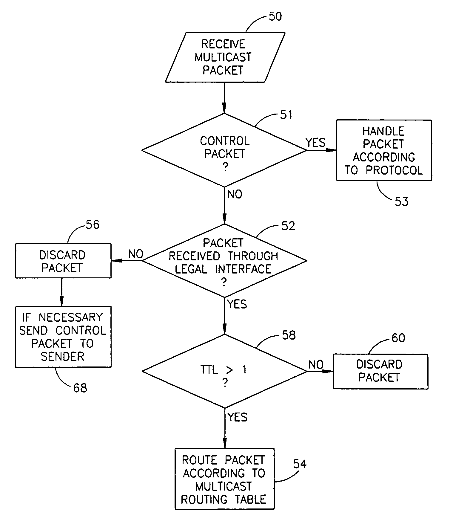
[0042]In some embodiments of the invention, layer-3 switches 34 do not bridge in layer-2 packets related to IF multicast routing protocols, even if the layer-2 addresses of the packets require such bridging. In some embodiments of the invention, the packets related to IP multicast routing protocols (referred to herein as IP multicast routing related packets) include IP multicast data packets and IP multicast...


PUM


Abstract

A method of determining local multicast information of a local area network (LAN), comprising dividing the LAN to a number of segments larger than the number of virtual LANs (VLANs) in the network and creating a layer-3 multicast routing table, which relates to each of the segments separately.

Description

FIELD OF THE INVENTION[0001]The present invention relates to communication networks and in particular to IP multicast in local area networks.BACKGROUND OF THE INVENTION[0002]Many Internet applications include transmission of large amounts of data from a single source to a plurality of destinations. These applications include, for example, video and audio conferencing and replicating databases and web sites. Using unicast transmission, such applications send a copy of each packet they generate to each of the subscribers separately. IP multicast allows transmission of the packets in a more bandwidth efficient manner. IP multicast may also be used in many-to-many transmission applications, such as in conference calls and distributed database applications.[0003]In the IP multicast scheme, a source transmits multicast packets which carry a destination IP address which identifies the multicast group to which the packets belong. Routers which receive the multicast packets, generally transf...

Claims


Application Information

Patent Timeline
Patent Type & Authority Patents(United States)
IPC IPC(8): H04L12/56
CPCH04L12/1886H04L45/16H04L12/4641
Inventor SHABTAY, LIORRODRIG, BENNY
Owner AVAYA TECH CORP
Why Eureka
Try Eureka