Rollover judging device

a judging device and rollover technology, applied in the direction of suspensions, instruments, pedestrian/occupant safety arrangements, etc., can solve the problems of complicated process and difficulty in showing how much it gets close to the threshold in actual vehicle driving tests

Active Publication Date: 2011-04-12
NEXGEN CONTROL SYST LLC
View PDF27 Cites 1 Cited by
  • Summary
  • Abstract
  • Description
  • Claims
  • Application Information

AI Technical Summary

Benefits of technology

[0013]The rollover judgment device in accordance with the present invention adjusts the magnitude of the angular velocity component measured by the angular velocity sensor on the basis of either of at least the acceleration component of the vehicle in its rightward or leftward direction and the acceleration component of the vehicle in its upward or downward direction, calculates the angle component by integrating with respect to time the adjusted angular velocity component, performs the predetermined multiplication and addition processes on the basis of this calculated angle component and the measured angular velocity component mentioned above, and outputs a signal indicating judgment of occurrence of a rollover when the addition result exceeds the preset threshold. Therefore, the rollover judging device can judge whether or not the vehicle is rolling over with a simple structure without using complicated processing such as processing based on a conventional two-dimensional mapping method. Furthermore, because the rollover judging device sets the threshold which is used as a criterion of the judgment of occurrence of a rollover as a fixed value other than a variable which is conventionally used, the rollover judging device can simplify the arithmetic processing, thereby improving its reliability.

Problems solved by technology

A problem is therefore that for each of the first quadrant and the third quadrant, a computation of the judgment threshold and a judging process are needed, and the process is complicated.
A further problem with the process using the two-dimensional mapping method in the above-mentioned conventional example (patent reference 1) is that it is difficult to show how much it gets close to the threshold in actual vehicle driving tests, i.e., to express the severity of the rollover phenomenon using a simple percentage.

Method used


Image

  • Rollover judging device
  • Rollover judging device
  • Rollover judging device

Examples


embodiment 1

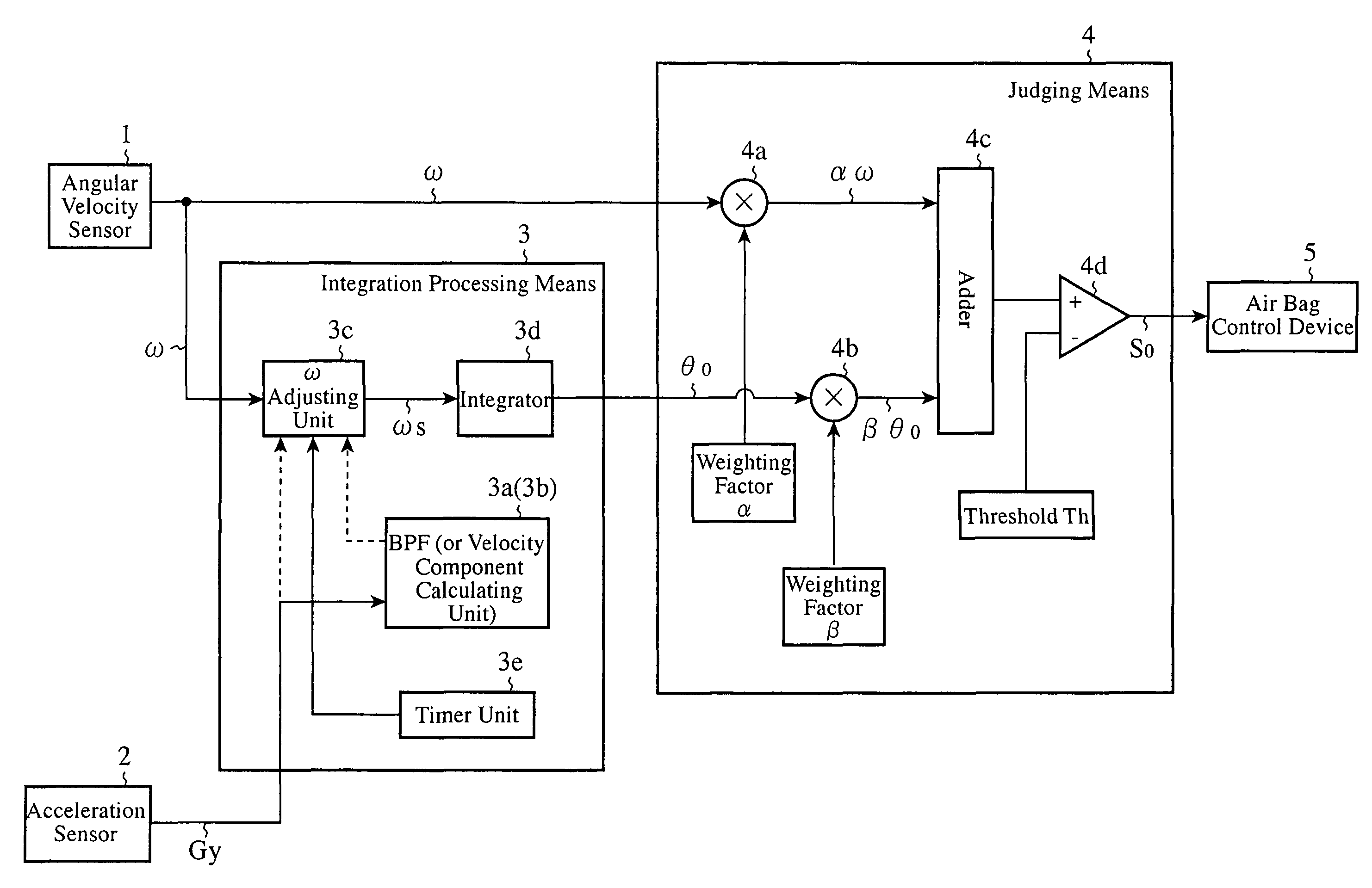
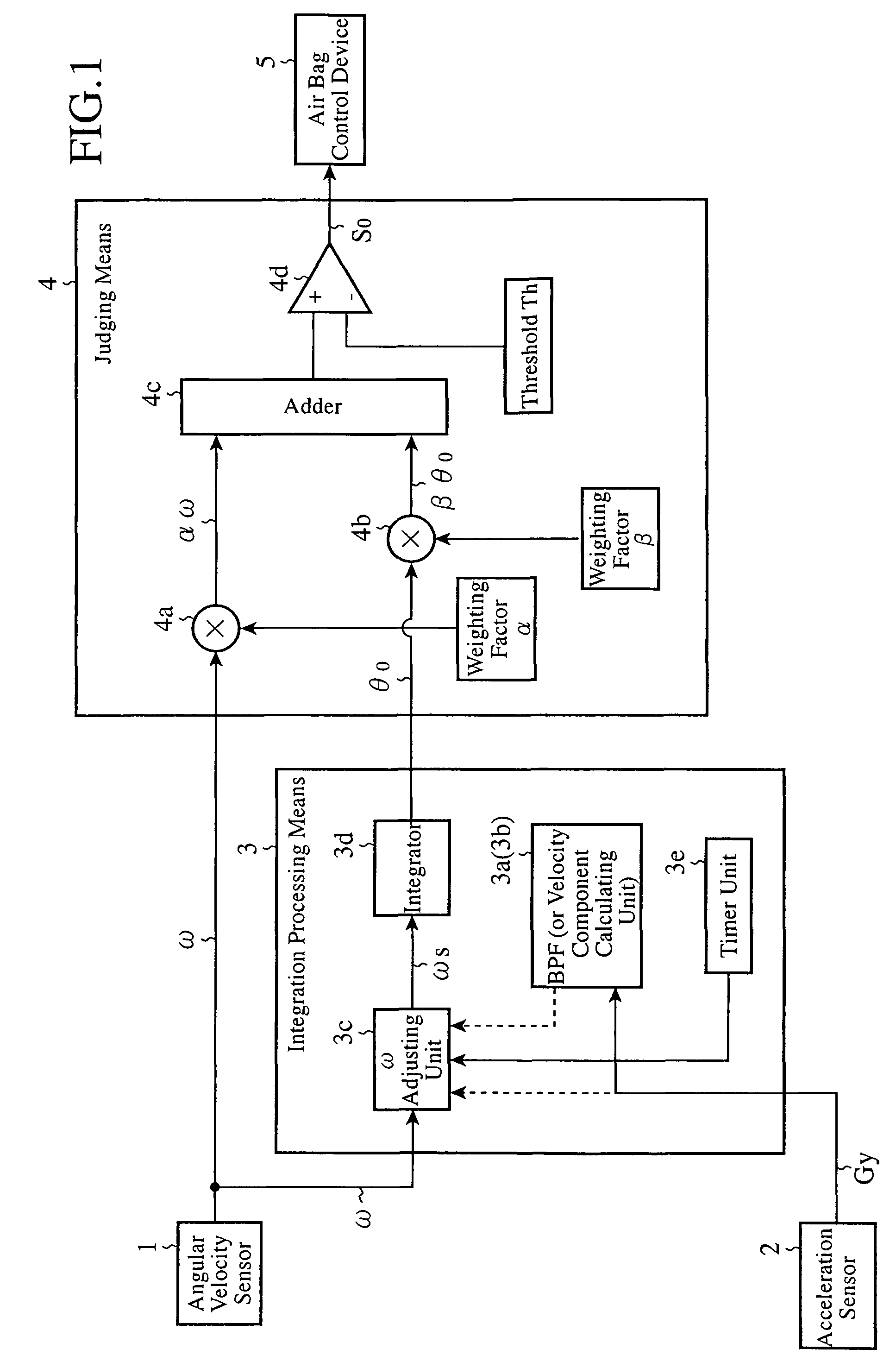
[0026]FIG. 1 is a block diagram showing the structure of a rollover judging device in accordance with Embodiment 1 of the present invention.

[0027]In FIG. 1, the rollover judging device in accordance with this Embodiment 1 is comprised of an angular velocity sensor 1, an acceleration sensor 2, an integration processing means 3, and a judging means 4. An air bag control device 5 is disposed as a next stage of this judging means 4.

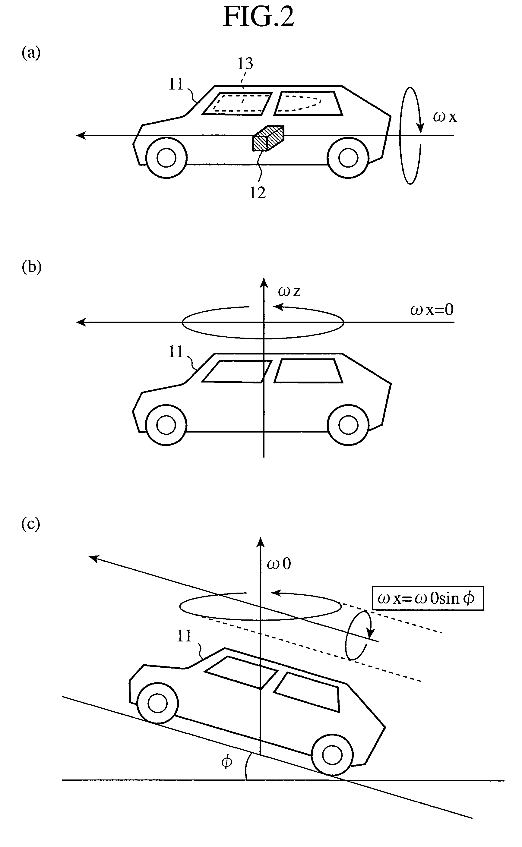
[0028]In the above-mentioned structure, the angular velocity sensor 1 measures an angular velocity component of a vehicle in a direction of the vehicle's rollover, and outputs a signal showing the angular velocity ω. This angular velocity sensor 1 is also called a roll rate sensor.

[0029]The acceleration sensor 2 measures at least either one of an acceleration component of the vehicle in a rightward or leftward direction of the vehicle and an acceleration component of the vehicle in an upward or downward direction of the vehicle. In the following explanation, ...

embodiment 2

[0145]FIG. 8 is a block diagram showing the structure of a rollover judging device in accordance with Embodiment 2 of the present invention. The same components as those shown in FIG. 1 are designated by the same reference characters, respectively.

[0146]The structure shown in FIG. 8 differs from that shown in FIG. 1 in that an integration processing means 21 is disposed instead of the integration processing means 3 of FIG. 1, and the other components are the same as those in the structure shown in FIG. 1.

[0147]The integration processing means 3 of FIG. 1 increases or suppresses the rate of the integration by adjusting the rate of the angular velocity ω, etc. on the basis of the occurrence pattern of the acceleration component Gy of the vehicle in its rightward or leftward direction which is measured by the acceleration sensor 2. In contrast, the integration processing means 21 of this FIG. 8 adjusts the amount of return which is used for integral value return-to-zero processing in a...

embodiment 3

[0202]FIG. 10 is a block diagram showing the structure of a rollover judging device in accordance with Embodiment 3 of the present invention. The same components as those shown in FIG. 1 are designated by the same reference characters, respectively.

[0203]In FIG. 10, the structure shown in this figure differs from that shown in FIG. 1 in that an integration processing means 31 is disposed instead of the integration processing means 3 of FIG. 1, and the other components are the same as those of the structure of FIG. 1.

[0204]The integration processing means 31 of this FIG. 10 adjusts an angle component on which integration processing has been performed according to the occurrence pattern of the acceleration component Gy of the vehicle in its rightward or leftward direction which is measured by the acceleration sensor 2.

[0205]Therefore, in the following explanation, the integration processing means 31 which is the above-mentioned difference will be mainly explained and the explanation o...


PUM


Abstract

A rollover judging device adjusts the magnitude of an angular velocity component ω of a vehicle in a direction of a rollover, which is measured by an angular velocity sensor 1, by using an ω adjusting unit 3c on the basis of an acceleration component of the vehicle in its rightward or leftward direction or in its upward or downward direction, which is measured by an acceleration sensor 2, calculates an angle component θo by integrating with respect to time this adjusted angular velocity component ωo by using an integrator 3d, carries out predetermined multiplication and addition processes by using a judging means 4 on the basis of this angle component θo and the measured angular velocity component ω, and, when the result of this addition process exceeds a preset threshold Th, outputs a signal indicating judgment of occurrence of a rollover to an air bag control device 5.

Description

FIELD OF THE INVENTION[0001]The present invention relates to a rollover (rollover) judging device which provides an improvement in its reliability using an occurrence pattern of the acceleration of a vehicle in a rightward or leftward direction or the like.BACKGROUND OF THE INVENTION[0002]In a rollover judging method for use in conventional rollover judging devices, a two-dimensional mapping method of mapping an angular velocity ω and a tilt angle θv is used, and a method of setting ON and OFF regions on mapping in advance, and of, when (ω, θv) is pointed in the ON region, triggering an occupant crash protection device, such as an air bag, is used. As a rollover judging device which employs another example of the two-dimensional mapping method, there is the following conventional example.[0003]In the mapping method for use in this conventional rollover judging device, in order to start an occupant crash protection according to a rotation of a vehicle in its rightward or leftward dir...

Claims


Application Information

Patent Timeline
Patent Type & Authority Patents(United States)
IPC IPC(8): B60R21/13G06F19/00
CPCB60R21/0132B60W30/04B60R2021/0018B60W2550/142B60R2021/01327B60R21/0133B60R21/01332B60W2552/15
Inventor YAMASHITA, TOSHIYUKIHARASE, SHINICHIINOUE, SATORUTOKUNAGA, TAKASHIFURUI, TAKASHI
Owner NEXGEN CONTROL SYST LLC
Why Eureka
Try Eureka