Modular unit

a modular unit and modular technology, applied in the direction of moving filter element filters, filtration separation, separation processes, etc., can solve the problems of increasing costs, tubing is associated with the corresponding complexity in production and installation, and the retrofitting of the further modular unit to the existing oil tank or tank unit is difficult, so as to achieve energy-efficient operation and economical implementation.

Active Publication Date: 2011-04-19
HYDAC FILTERTECHNIK GMBH
View PDF23 Cites 8 Cited by
  • Summary
  • Abstract
  • Description
  • Claims
  • Application Information

AI Technical Summary

Benefits of technology

[0004]An object of the present invention is to provide improved modular units that are compact, can be retrofitted onto existing tank units and are interchangeable, and permit energy-efficient operation and economical implementation.

Problems solved by technology

In particular, retrofitting onto existing oil tanks or tank units with the further modular unit is hardly possible.
As already explained, this tubing is associated with the corresponding complexity in terms of production and installation.
This tubing also raises costs, and flow resistances arise due to the length of the fluid lines provided between the modular unit and the tank unit.
This arrangement has adverse effects on the energy-efficient operation of the means as a whole.
The additional fluid lines also result in increased installation space.
In applications in automotive and mechanical engineering and apparatus engineering, this arrangement often leads to problems, where often there is only little installation space due to given boundary conditions.

Method used


Image

  • Modular unit
  • Modular unit
  • Modular unit

Examples


Embodiment Construction

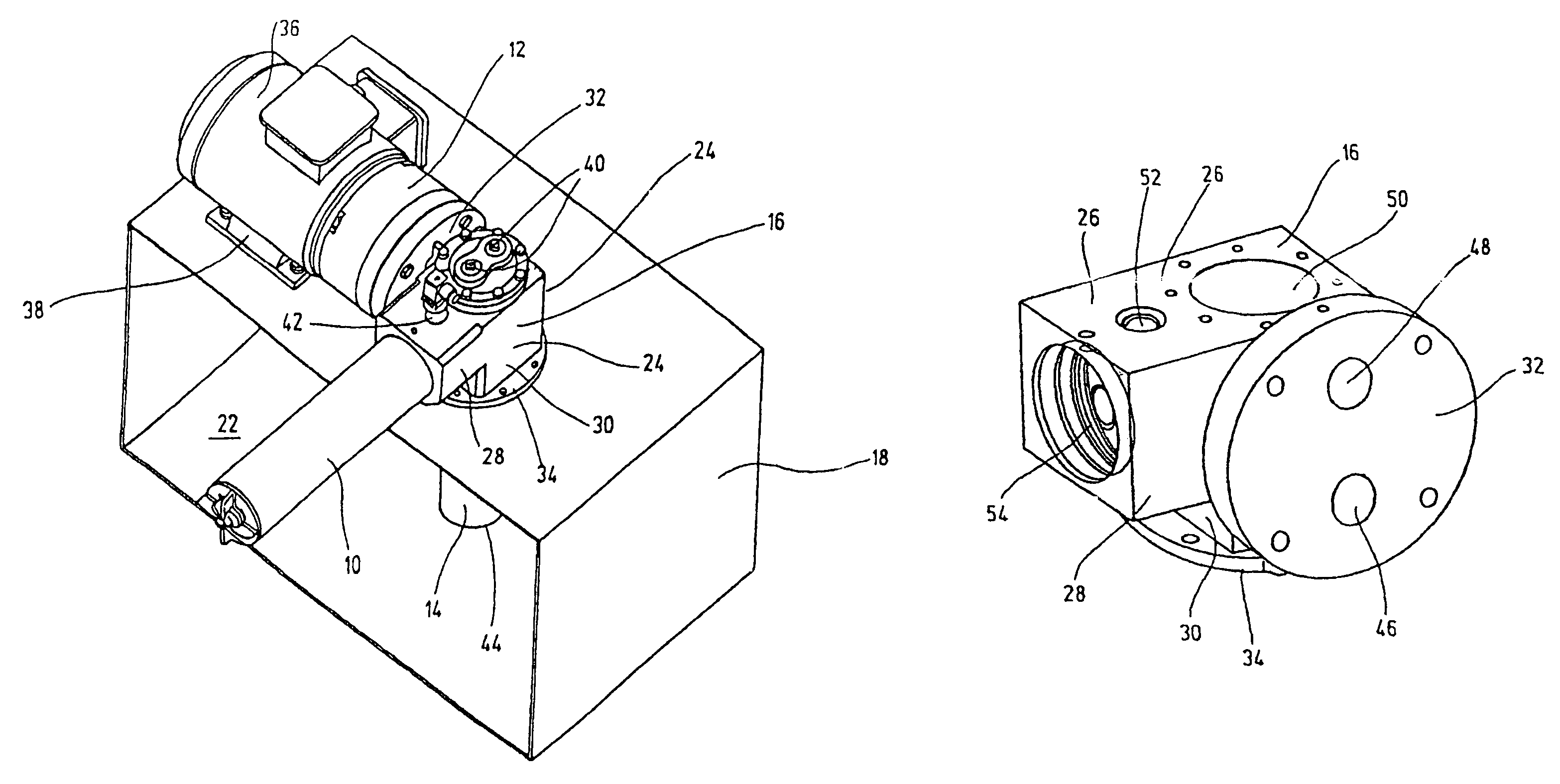
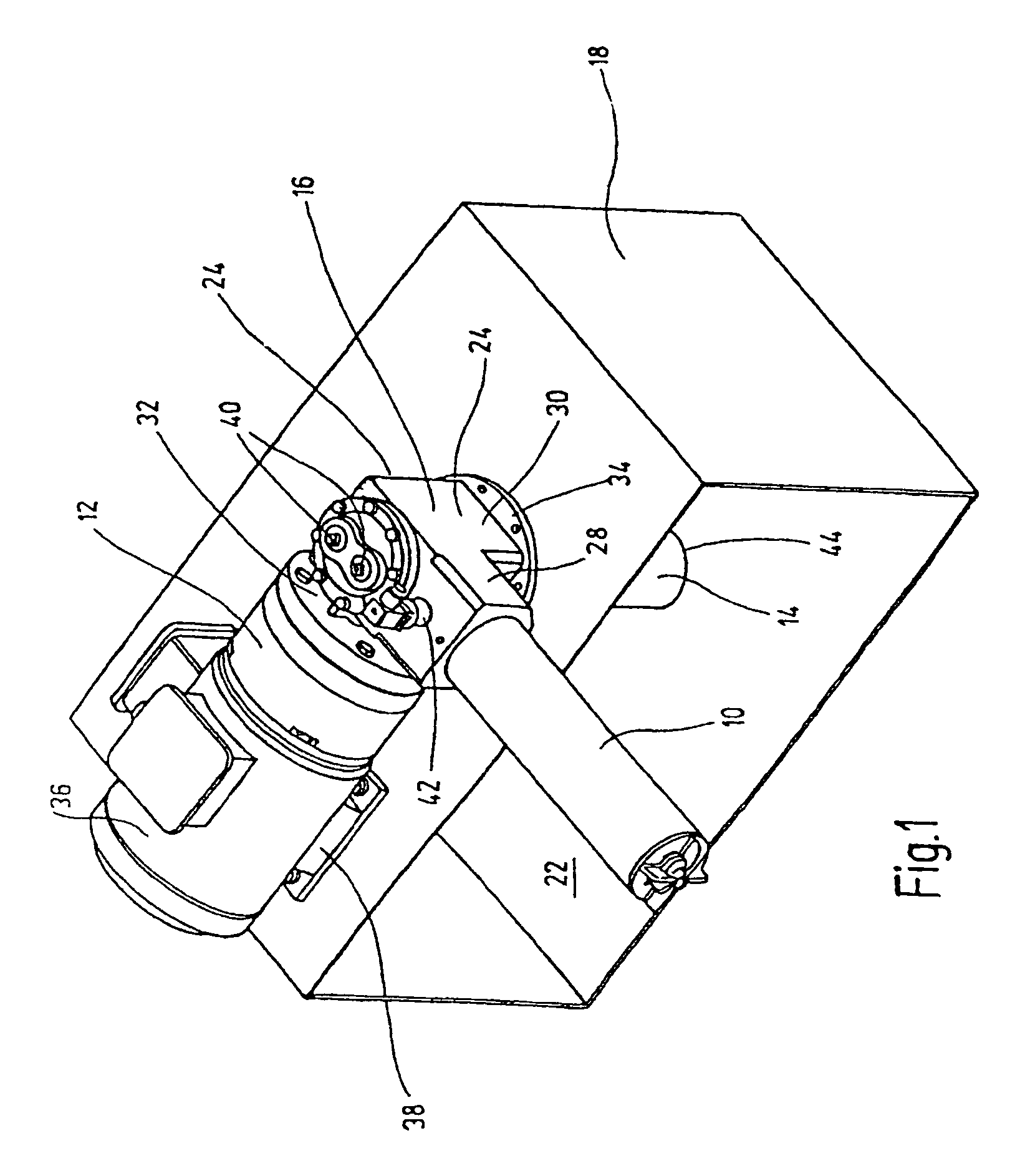
[0017]The modular unit shown as a whole in FIG. 1 has a filter unit 10, a pump unit 12 and a cooling unit 14 (shown only partially). These units can be connected to one another to carry fluid by a connecting module 16 and can be connected to a tank unit 18. The tank unit 18 preferably constitutes an oil tank with hydraulic oil as the fluid medium. The modular unit of the present invention can also be used for other fluid media, such as water, special alcohols, gasoline, etc. The tank unit 18 shown in FIG. 1 is made as a rectangular container, the face-side wall toward the viewer having been omitted to illustrate the engagement of the cooling unit 14 with the tank unit 18.

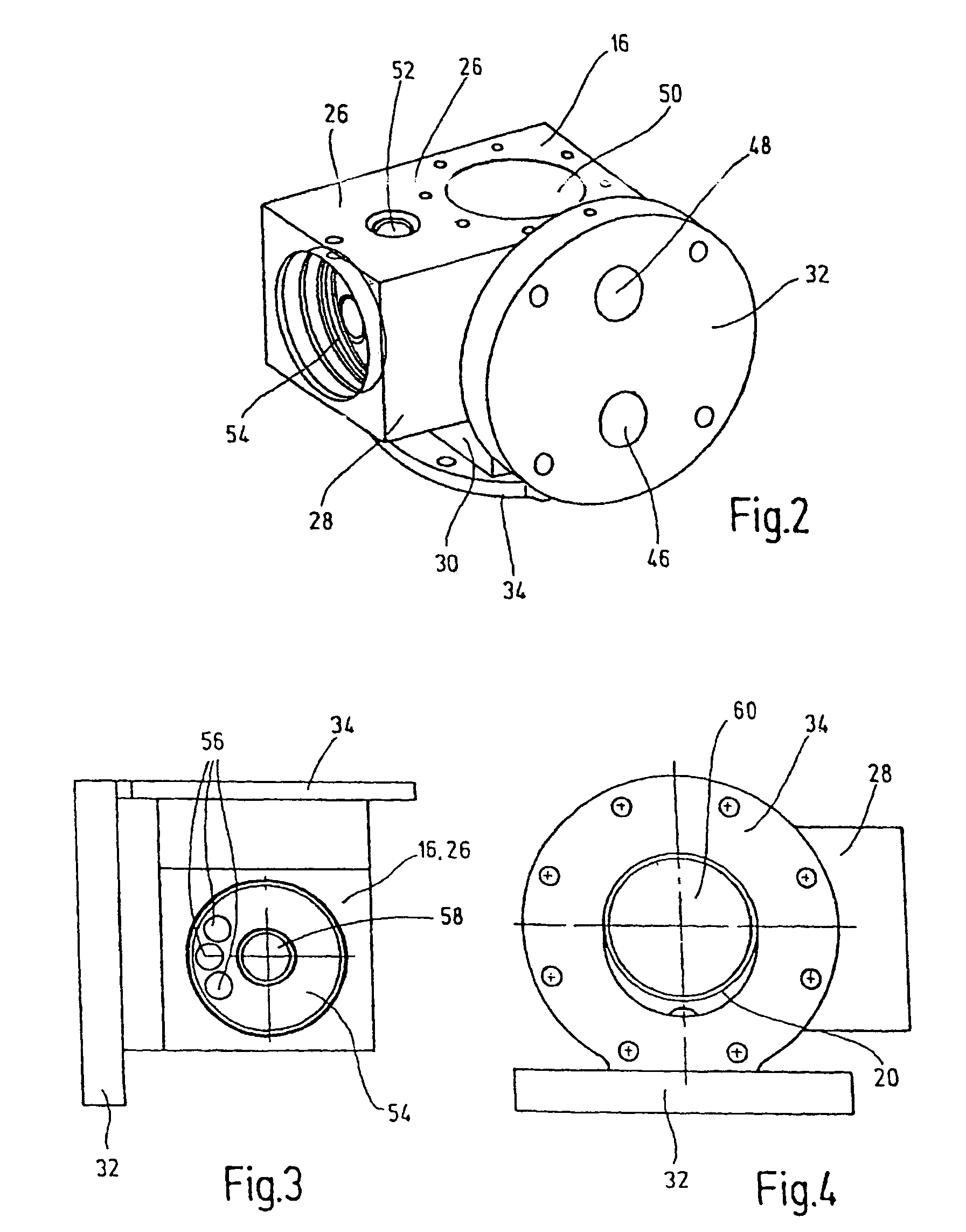
[0018]The connecting module 16 with the tank unit 18 connected projects with an intake opening 20 (compare FIGS. 4 and 6) together with the cooling unit 14 into the interior 22 of the tank unit 18. The pump unit 12 is located outside of the tank unit 18. In the embodiment as shown in FIG. 1, the three units 10, 12, ...


PUM

PropertyMeasurementUnit
pressureaaaaaaaaaa
shapeaaaaaaaaaa
volumeaaaaaaaaaa

Abstract

A modular unit has at least one filter (10), pump (12) and cooling unit (14) fluidically connected to each other by a connection module (16) and connected to a tank unit (18). The connection module (16) opens out inside (22) the tank unit with a suction opening (20), together with the cooling unit (14) when the tank unit is connected (18). The filter unit (10) and pump unit (12) are arranged outside the tank unit (18). The modular unit can then be placed on and connected to a tank unit. The cooling unit protrudes inside the tank unit.

Description

FIELD OF THE INVENTION[0001]The present invention relates to a modular unit having at least one filter unit, one pump unit and one cooling unit connected to each other to carry fluid by a connecting module and connected to a tank unit.BACKGROUND OF THE INVENTION[0002]WO 98 / 42986 A1 discloses a fluid cooling device as a modular unit with a motor which drives a fan wheel and a fluid pump which takes fluid from an oil tank and delivers it to a hydraulic working circuit which heats the fluid. The fluid pump routes the fluid to a heat exchanger (cooling unit). From the heat exchanger the cooled fluid is returned to the oil tank. The oil tank is made trough-shaped and with raised trough edges partially encompassing at least the motor and the fluid pump in the shape of a half shell. With the known solution, the actual modular unit of a filter unit, a pump unit and a cooling unit can be connected in a space-saving manner to a relatively high-volume oil tank as the tank unit. From the instal...

Claims


Application Information

Patent Timeline
Patent Type & Authority Patents(United States)
IPC IPC(8): F15B13/00F15B1/26F15B21/041F15B21/0423
CPCF15B1/26F15B21/042F15B21/041Y10T137/87885Y10T137/86035Y10T137/6416F15B21/0423F15B21/04
Inventor JUNG, ARTURSANN, NORBERT
Owner HYDAC FILTERTECHNIK GMBH
Why Eureka
Try Eureka