Apparatus for receiving and transferring kinetic energy from a flow and wave

a technology of fluid basin and apparatus, which is applied in the direction of hydro energy generation, non-positive displacement fluid engine components, liquid fuel engine components, etc., can solve the problems of absorbing the shock energy of the blades, requiring a rotatory motionless support, and a large shroud capturing the turbines

Inactive Publication Date: 2011-04-19
SHREIDER VLADIMIR ANATOL +1
View PDF83 Cites 16 Cited by
  • Summary
  • Abstract
  • Description
  • Claims
  • Application Information

AI Technical Summary

Benefits of technology

[0014]A first embodiment of the apparatus according to the present invention for receiving and transferring kinetic energy of a fluid flow follows the general idea of utilizing a tandem axial turbine unit comprising co-axially disposed a rotatable front axial turbine runner of relatively big diameter and a rotatable rear axial turbine runner of relatively small diameter, where the front runner is capable of directing and speeding an oncoming part of the main flow toward the rear runner and comprises a plurality of blades for receiving the oncoming fluid flow energy, a funnel-shaped member supporting and guiding the blades and capable of urging the oncoming flow in axial and converging radial and tangential directions, and forming a relatively low pressure zone in the outer main flow immediately adjacent to and downstream of the unit for further accelerating the oncoming flow in relation to the blades of the front and rear runners which rotate in opposite directions, where the confusor portion has the cone angle equal to about 30° to 40° and each of the front blades is extending along a line diverging at an angle which increasing in the axial direction from about 30° to 45°, and having the radial dimension that being equal to about 25-30% of an inner diameter of the confusor portion. A co-axially disposed, water-cleaning curtain lattice is fixedly mounted with its outer rear edge to and between and ahead of the front edge of the funnel for retention of weeds and debris's carried by the oncoming fluid flow, and an elongate, lattice-cleaning scraper is co-axially disposed immediately ahead of the lattice and supported rotatably about the axis on the pin and extending toward the edge and having the center of gravity being located under of the axis and a cutting edge oriented in a direction opposite the direction of rotation of the lattice thereby the scraper can remove debris's delayed by the lattice member; and an axially disposed pin supporting the front and rear runners for relative rotation and having a front end; and a means for connecting the front pin end to stopper objects, where the main flow is moving relative to the stopper objects, capable of maintaining the unit in operative positions in the main flow.
[0019]The runner comprises pivoting springs capable to individually control the position of each blade within a certain range of the pivotal positions and adapted for transferring the kinetic energy from the lower ambient flow as the blade pivots from the lower to the upper position and pivoting the blade vice versa, each of the springs is integrally connected with its ends to the blade and to the hub to effect pivoting of the blade between stops, and is capable of forcing the hub against the blade and the lower ambient flow to effect the transferring of the energy, and a pair of the stops permit pivotal movement of the spring with the blade relative to the hub between the upper and lower positions.
[0021]a front, shroud interior room-forming apron having first and second opposing ends in a close facing relationship to respective inside faces of the side walls and an forward and upward oriented side edge extending between the side walls and being supported pivotally at the upper edge in a close facing relationship on the lower edge of the front wall and capable of floating on the water surface and pivoting about an axis within the lower and upper front edges and parallel to the axis of the runner between a backward oriented horizontal position and a downward oriented position; a rear, shroud interior room-forming apron having first and second opposing ends in a close facing relationship to respective inside faces of the side walls and a rearward and upward oriented side edge extending between the side walls and being supported pivotally at the upper edge in a close facing relationship on the lower edge of the rear wall and capable of floating on the water surface and pivoting about an axis within the lower and upper rear edges and parallel to the axis of the runner between a forward oriented horizontal position and a downward oriented position; a sealing packing means located outside on the ends of the aprons for engaging on the inside faces of the side walls to close-off the interior of the room in relation to its exterior and prevent the outflow of air from the room into outside; whereby movement of the air into and out of the room displaces the surface of the water located in the room in a corresponding vertical direction within a radial width of a lowermost blade of the runner and pivots the aprons follow the water surface about their pivot axes, and thereby changes a depth of sinking of the blades into the jet and a magnitude of the kinetic energy which being received by the blades from the jet.
[0022]In another aspect the present invention provides a method of water flow-creating useable energy by transforming a water flow induced rotation of the second tangential fluid turbine runner into an amplified motion of a energy-generating member of an useable energy generator, the method comprising the steps of utilizing the second embodiment of the tangential water turbine unit, and operating an activating means of the source of compressed air to displace air in an intended sense in relation to the interior of the shroud room and to displace a surface of the water in an intended vertical direction within a radial width of a lowermost blade of the runner to cause the water to flow between the apron with the sealing means engaging the side walls and press on an intended surface of the lowermost blade.
[0030]The system comprises a number of reversible machines, each of the machines is connected to the first member and to the second member therebetween and capable of generating an intended useable energy and restraint the relative movement between the ends of the first and second members. The machine is a cylinder and sliding vane motor-pump assembly comprising a circular cylindrical shaft member having first and second opposing end pin portions and at least one pumping and damping vane portion extending radially, in relation to an axis of the shaft member, between the first and second pin portions, where each of the vane portions has a first end and a second end and an outer edge extending between the first and second edges toward immediately an inner face of a pumping and damping cylinder member of the assembly, the co-axially disposed pumping and damping cylinder member having two opposing, radially extending end walls that being provided with axial openings generally surrounding the pin portions of the shaft member and a circular cylindrical wall extending between the end walls and having vane portions extending between end walls radially inward and toward immediately an outer face of the shaft member, a sealing means at the openings and edges of the vane portions of the shaft and cylinder members for engaging on the faces of the cylinder and shaft members to relatively close off interiors between the vane portions of the cylinder and shaft members and prevent the outflow of the fluid materials being compressed from the interiors being reduced into the adjacent interiors being extended; a valves and pipes for sucking the fluid materials into the interior being extended and exhausting the compressed fluid materials from the interior being reduced toward a reserve tank receiving and storing the compressed fluid materials, where the valves are capable of tuning the generating-pumping system or shutting it down; the tank provided with valves and pipes for transferring the compressed fluid materials toward an user, where the valves are capable of changing pressure of the stored fluid materials for tuning the generating-pumping system or shutting it down.

Problems solved by technology

a dual turbine unit suggested with E.U. Patent Application PCT WO No. 02 / 27151 A1 and counteracts rotational counter-torque of side-by-side disposed fluid turbines, but has the disadvantage such as a heavy shroud capturing the turbines; and
a conical turbine body described with Australian Patent Application No. 587780 filed of May 11, 1985 which increasing in radial dimension and having a plurality of blades spaced outside and around the body and providing channels diverging tangentially from axial planes, but having the disadvantages such as a rotational counter-torque, relative small speed of rotation, needing of a rotatory motionless support.
WO 9961791 filed Dec. 2, 1999 that is provided with blades rotatable by the flow through 180° between positions across and along the flow and has the disadvantage such as needing of a damping means for absorbing shock energy of the blades.
a known from U.S. Pat. No. 6,561,856 of May 13, 2003 wave-powered ship propulsion system comprising a gyroscopically stabilized platform carried by a ship and isolated from a pitching motion of the ship; the disadvantages of this technology are relative short distance of a moment of force and therefore needing a large size gyroscope, and to control a gyro precession;
The disadvantage is that the stabilizers are not capable of stabilizing a rolling motion of the ship.

Method used


Image

  • Apparatus for receiving and transferring kinetic energy from a flow and wave
  • Apparatus for receiving and transferring kinetic energy from a flow and wave
  • Apparatus for receiving and transferring kinetic energy from a flow and wave

Examples


first embodiment

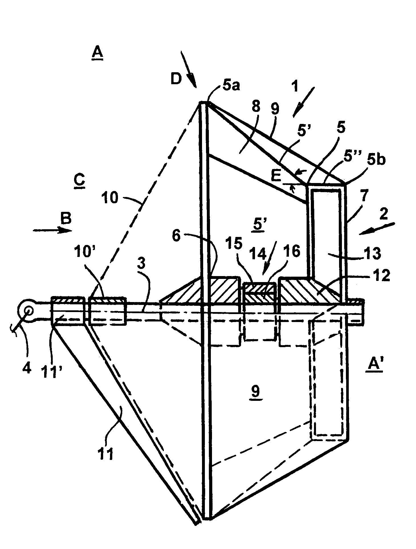
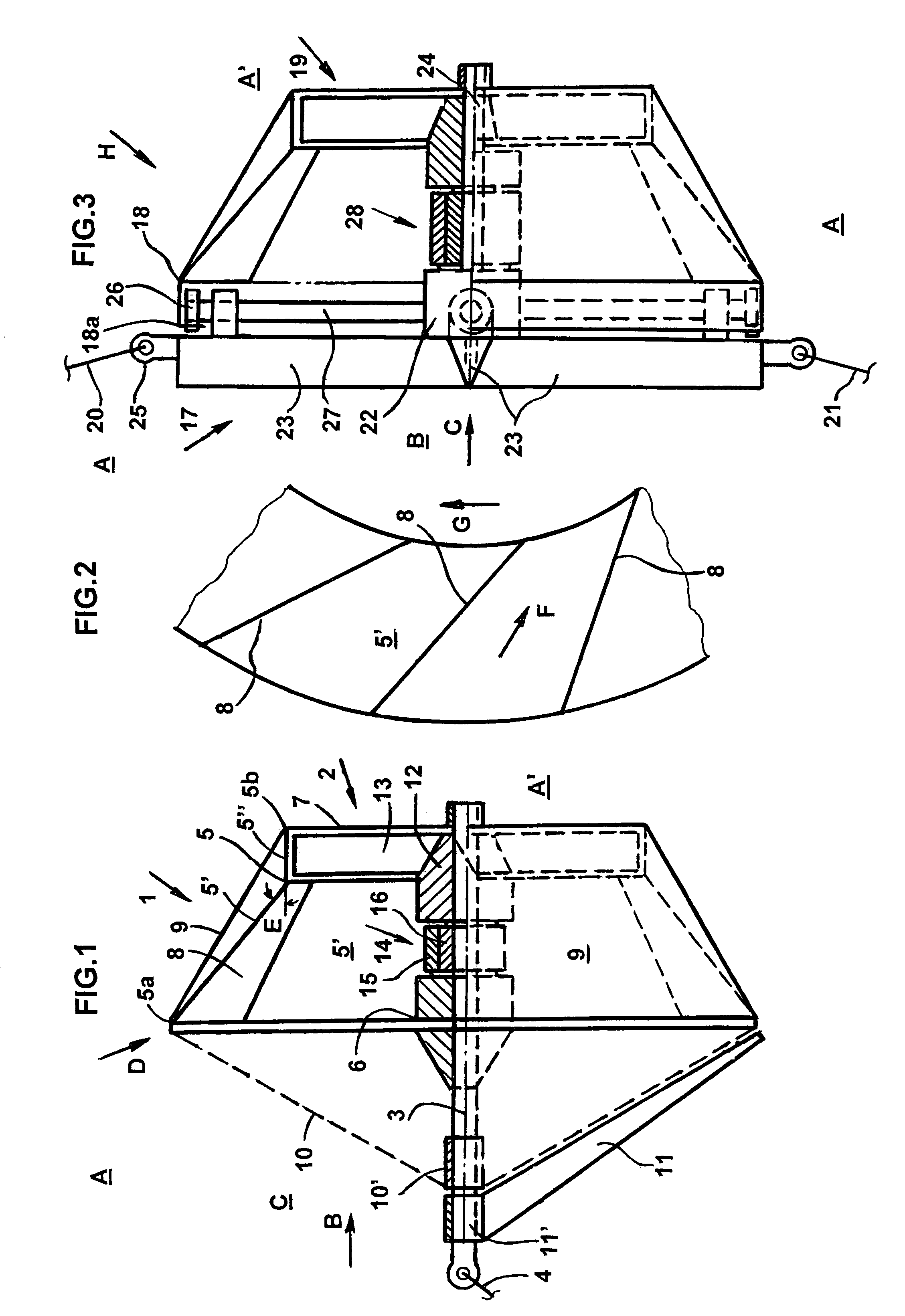
[0044]the apparatus according to the invention includes a tandem axial fluid turbine unit B as illustrated in FIG. 1, adapted to submerge and capable of being maintained in a path of, the main flow A and comprising a relatively widened, rotatable front axial turbine runner assembly 1 capable of facing, directing and speeding an oncoming fluid flow C; a relatively narrowed, rotatable rear co-axial turbine runner assembly 2; an axially and horizontally disposed, elongate pin member 3 supporting the assemblies 1 and 2 for relative rotation about a central longitudinal axis of the assemblies 1 and 2 and the member 3, the axis being oriented in the direction B, an elongate tether member 4 of a means supporting the unit D in operative positions within the path of the water flow A and described more fully hereinafter, connected with its rear end to the front end of the member 3 provided with a well-known swivel.

[0045]The assembly 1 comprises a funnel-shaped member 5 disposed along the dire...

second embodiment

[0051]the invention is a tandem axial fluid turbine unit H as illustrated in FIG. 3, comprises a vertically disposed, spider-shaped frame 17 for supporting components of the unit H, a front axial fluid turbine runner assembly 18 and a rear axial fluid turbine runner assembly 19, where the assemblies 18 and 19 can be similar in construction to the assemblies 1 and 2 of the unit D, elongate first tether member 20 and second tether member 21 for maintaining the unit H within the path of the flow A in operative positions in relation to the stopper objects (described more fully hereinafter).

[0052]The frame 17 is composed of a central body 22, a plurality, preferably four of the same elongate consoles 23 extended radially from the body 22 horizontally leftward and rightward, and preferably vertically and configured openings therebetween; an axial axle 24 supporting and guiding the assemblies 18 and 19 for rotation, left and right means 25 provided on ends of the horizontal consoles 23 for...


PUM


Abstract

A tandem axial turbine that comprises a front confusor, a funnel-shaped runner having inner blades and capable of accelerating and directing an oncoming flow toward a co-axial rear runner which rotates in an opposite direction. A tangential turbine has a hub, blades capable of rotating in relation to the hub between positions across and along the flow, and propulsion springs for controlling the movement of the blades in relation to the hub and the transfer of the energy. A second tangential turbine comprises a runner having a hub and blades and a shroud capturing the runner from above and around and permitting the blades to dip into water flowing immediately below the hub and an opening of the shroud. A surface vessel comprises a stabilized frame rotatably affixed on a vessel hull about a center of wave induced rocking motions of the vessel and therefore isolated from a rocking motion of the vessel.

Description

CROSS-REFERENCE TO RELATED APPLICATIONS[0001]Not ApplicableSTATEMENT REGARDING FEDERAL SPONSORED R and D[0002]Not ApplicableREFERENCE TO A MICROFICHE APPENDIX[0003]Not applicableBACKGROUND OF THE INVENTION[0004]The invention relates to apparatuses for receiving and transferring kinetic energy of a fluid basin, especially a water basin into any useable power and to submersible axial fluid turbines as defined in claim 1.[0005]There exists a need for effective, high-speed hydro-turbine units which do not require substantial vehicular support for deployment or retrieval and can be placed in a particular optimal operative position in a path of water flow, then easily maneuvered to a different position within the water flow in the event of a change of location of the optimal path and stabilized in the path without complex anchoring means.[0006]For claim 1 here are considered as the nearest to the invention:[0007]a dual turbine unit suggested with E.U. Patent Application PCT WO No. 02 / 2715...

Claims


Application Information

Patent Timeline
Patent Type & Authority Patents(United States)
IPC IPC(8): F03B13/00H02P9/04F03B13/10
CPCF03B11/08F03B13/20F03B17/06Y02E10/38F05B2250/323Y02E10/28F05B2250/311Y10S415/905Y10S415/907Y02A20/144Y02E10/30Y02E10/20
Inventor SHREIDER, VLADIMIR ANATOLSHREIDER, NATALIA
Owner SHREIDER VLADIMIR ANATOL
Why Eureka
Try Eureka