Piezoelectric transducer, piezoelectric actuator, and portable device

a technology of piezoelectric actuator and piezoelectric transducer, which is applied in the direction of generating/distributing signals, instruments, horology, etc., can solve the problems of increasing the applied voltage to increase the amplitude, reducing the amplitude, and requiring a larger power supply to achieve the desired drive characteristic. achieve the effect of improving the drive efficiency

Inactive Publication Date: 2011-04-19
SEIKO EPSON CORP
View PDF25 Cites 45 Cited by
  • Summary
  • Abstract
  • Description
  • Claims
  • Application Information

AI Technical Summary

Benefits of technology

As a result of studying the shape of the reinforcing member and the vibration energy density in different parts of the reinforcing member, the piezoelectric transducer, the piezoelectric actuator, and a portable device according to the present invention can greatly improve the drive efficiency.
A portable device according to the invention also realizes the benefits of a piezoelectric actuator, including quick response and not being affected by magnetism.

Problems solved by technology

The applied voltage drops if the size of the power supply (battery) is reduced, the amplitude therefore also decreases, and it is difficult to achieve the desired drive characteristic.
Conversely, increasing the applied voltage to increase the amplitude typically requires a larger power supply.
Note that as the size of the power supply decreases and the applied voltage decreases, vibration of the piezoelectric element decreases and the drive efficiency relative to the input power drops, and driving the driven body may not be possible.
Unless the significance of the different shapes of low rigidity reinforcing members is better understood, reliably increasing amplitude in a specific vibration mode and achieving high drive efficiency will not be possible.
Vibration of the piezoelectric transducer is also impeded and vibration efficiency drops with the devices taught in JP-A-H08-114408 and JP-A-H06-104503 because the reinforcing member and the piezoelectric element are in contact at the antinode of the sinusoidal vibration where the strain of sinusoidal vibration is greatest.
However, because the shape of the part (this part is referred to as the arm parts in Japanese Patent 3832260) of the reinforcing member extending substantially lengthwise through the widthwise center part of the rectangular piezoelectric element is not particularly considered and this part is narrow in width, the reinforcing member may not be able to limit displacement in any direction other than the direction (in-plane direction) along the plane perpendicular to the direction of the field applied to the piezoelectric element.
As a result, it may not even be possible to achieve the desired effect of increased amplitude.
As a result, displacement in a direction other than the in-plane direction (i.e., the out-of-plane direction) results if the size of the voids is increased indiscriminately.

Method used


Image

  • Piezoelectric transducer, piezoelectric actuator, and portable device
  • Piezoelectric transducer, piezoelectric actuator, and portable device
  • Piezoelectric transducer, piezoelectric actuator, and portable device

Examples


first embodiment

Preferred embodiments of the present invention are described below with reference to the accompanying figures. Note that like parts are identified by the same reference numerals used in the first embodiment, and further detailed description thereof is omitted or simplified in the second and other embodiments.

embodiment 1

This embodiment of the invention uses a wristwatch with a chronograph as an example of a portable device. This embodiment of the invention enables increasing the amplitude of longitudinal vibration, and can thereby also increase the amplitude of sinusoidal vibration.

1. General Configuration

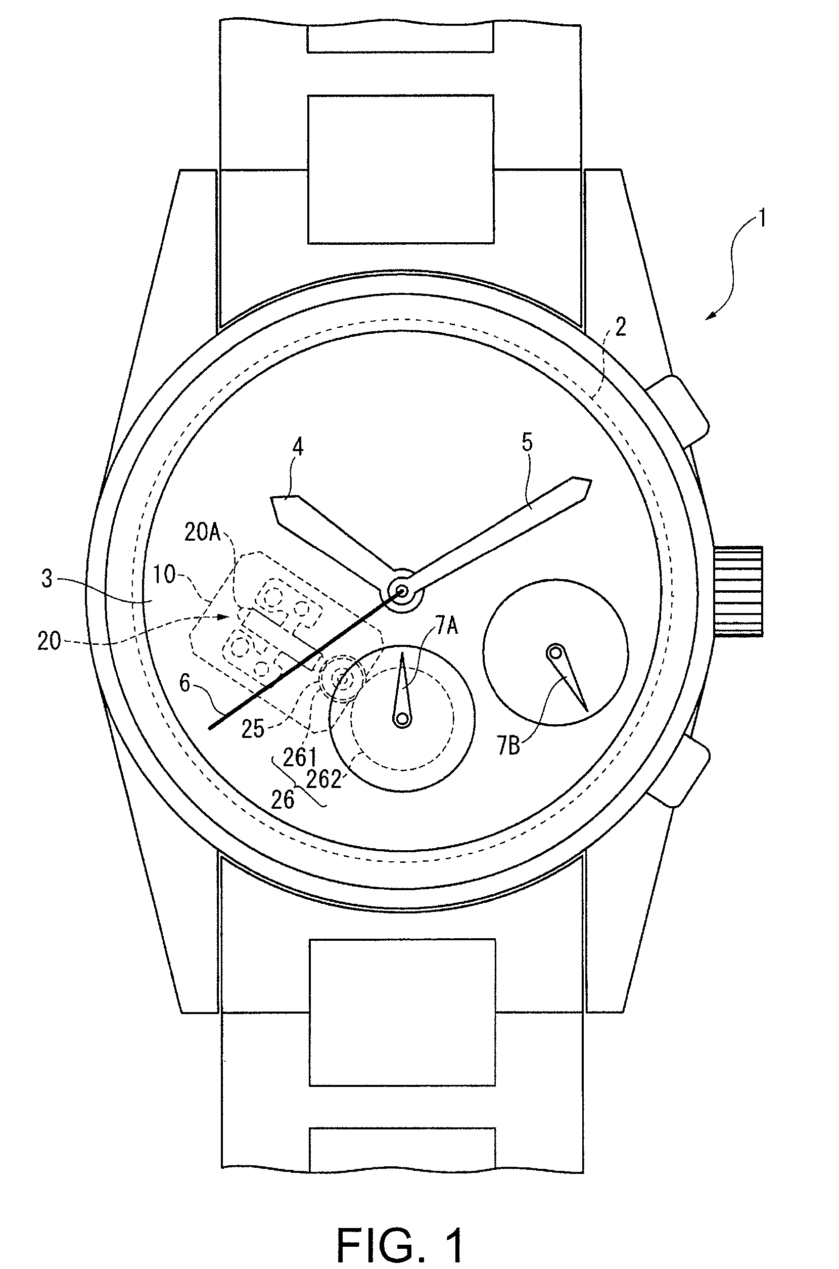
FIG. 1 is a plan view of a timepiece 1 according to this embodiment of the invention. This timepiece 1 has a movement 2, a dial 3, an hour hand 4, a minute hand 5, and a second hand 6 for displaying the time, and chronograph second hand 7A and chronograph minute hand 7B for showing the chronograph time.

The hour hand 4, minute hand 5, and second hand 6 are the same as in a conventional quartz watch, and are driven by a circuit board having a crystal oscillator, a stepping motor having a coil, stator, and rotor, a drive wheel train, and a battery.

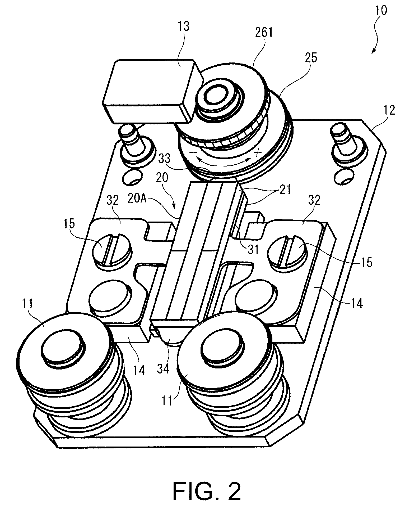
2. Chronograph Second Hand Drive Mechanism

The drive mechanism that drives the chronograph second hand 7A includes a piezoelectric transducer 20A, a rotor 2...

second embodiment

A second embodiment of the invention is described next. The arrangement of this embodiment of the invention enables increasing the amplitude of longitudinal vibration and sinusoidal vibration.

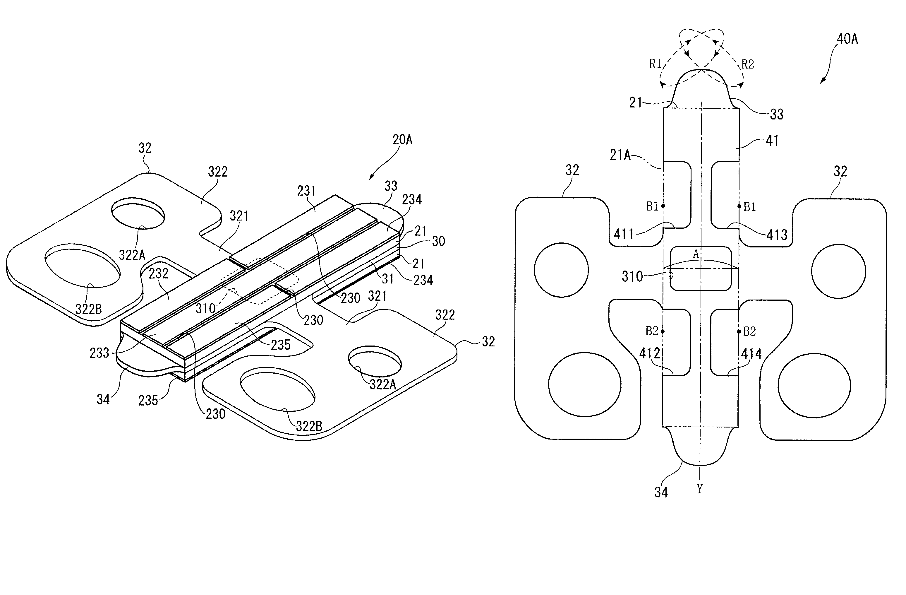
FIG. 10 shows a piezoelectric transducer 40A according to this embodiment of the invention. This embodiment differs from the first embodiment only in the shape of the reinforcing plate 41 that is layered with the piezoelectric elements 21, and is otherwise the same as the first embodiment.

In addition to having a through-hole 310 substantially identical to the first embodiment, the reinforcing plate 41 in this embodiment of the invention also has recesses 411 to 414 formed on both long sides of the reinforcing plate 41. These recesses 411 to 414 are formed as voids proceeding from the edges of the reinforcing plate 41 corresponding to the outside lengthwise edges 21A of the piezoelectric elements 21 to the inside across the width of the piezoelectric element 21. The recesses 411 to 414 are line ...


PUM


Abstract

A piezoelectric transducer that excites longitudinal vibration has a piezoelectric element, and a reinforcing member that is laminated with and affixed to the piezoelectric element and has a first void part. The first void part includes the center part of a location where strain produced by longitudinal vibration in the piezoelectric transducer or the reinforcing member or piezoelectric element is greatest.

Description

BACKGROUND1. Technical FieldThe present invention relates to a piezoelectric transducer, a piezoelectric actuator, and a portable device.2. Related ArtIn addition to reducing the size and thickness of parts used in small, portable electronic devices such as wristwatches, it is also conventionally desirable to reduce power consumption in order to extend battery life. This has led to piezoelectric actuators being used instead of stepping motors as the drive device in timepieces, for example, because of their small size, thinness, and superior efficiency converting electrical energy to mechanical energy. See, for example, Japanese Patent 3832260 (FIG. 6 and paragraphs 0008 and 0009), Japanese Unexamined Patent Appl. Pubs. JP-A-H08-114408 (FIG. 7), JP-A-H06-104503 (FIG. 1), JP-A-2004-254417 (FIG. 2 and FIG. 7), and WIPO Pamphlet 96 / 14687 (page 14, lines 15-24, and FIG. 16).As shown in Japanese Patent 3832260, the piezoelectric actuator used in this type of portable device has a flat, su...

Claims


Application Information

Patent Timeline
Patent Type & Authority Patents(United States)
IPC IPC(8): G04F5/00H01L41/08H02N2/10
CPCH01L41/0906G04C3/12H02N2/004H02N2/103
Inventor YAMAZAKI, YUTAKA
Owner SEIKO EPSON CORP
Why Eureka
Try Eureka