Vehicle braking control

a technology of vehicle braking and control, applied in electrical control, non-mechanical valves, instruments, etc., can solve the problems of reducing the effectiveness of downstream exhaust catalysts, insufficient vacuum level in intake manifolds, and inventors' recognition of disadvantages of this approach, so as to increase the vacuum in intake manifolds

Active Publication Date: 2011-04-19
FORD GLOBAL TECH LLC
View PDF14 Cites 208 Cited by
  • Summary
  • Abstract
  • Description
  • Claims
  • Application Information

AI Technical Summary

Benefits of technology

[0001]Some vehicles may include engines that are configured to shut-off the fueling and the ignition system of one or more of the cylinders during deceleration events also known as deceleration fuel shut-off (DFSO) in an effort to achieve improved fuel economy and reduced emissions. During these DFSO events, intake air not participating in combustion, may pass through the engine via one or more deactivated cylinders where it may reduce the effectiveness of a downstream exhaust catalyst via catalyst cooling and / or oxidant saturation.
[0002]In one approach, an engine including intake and exhaust valves having electric valve actuation may close the intake valves of the deactivated cylinders to reduce airflow through the engine while the exhaust valves are controlled to modulate torque output. Similarly, engines having exhaust valves that are cam actuated may utilize a deactivation device for closing a sub-set of the exhaust valves. For example, the exhaust valves of one of the two cylinder banks of an eight cylinder engine may be closed during a DFSO event to reduce airflow through the engine.
[0005]In this way, deceleration control may be achieved while reducing oxygen to the exhaust and providing sufficient intake manifold vacuum by adjusting valve operation depending on vacuum conditions. Further, in some conditions, operation of an intake throttle may be coordinated with valve operation to provide increased intake manifold vacuum while providing the desired braking of the vehicle.

Problems solved by technology

During these DFSO events, intake air not participating in combustion, may pass through the engine via one or more deactivated cylinders where it may reduce the effectiveness of a downstream exhaust catalyst via catalyst cooling and / or oxidant saturation.
However, the inventors have recognized a disadvantage with this approach.
Specifically, during some DFSO events, the intake manifold may not have a sufficient vacuum level to operate other vehicle systems such as the vehicle's brakes.

Method used


Image

  • Vehicle braking control
  • Vehicle braking control
  • Vehicle braking control

Examples


Embodiment Construction

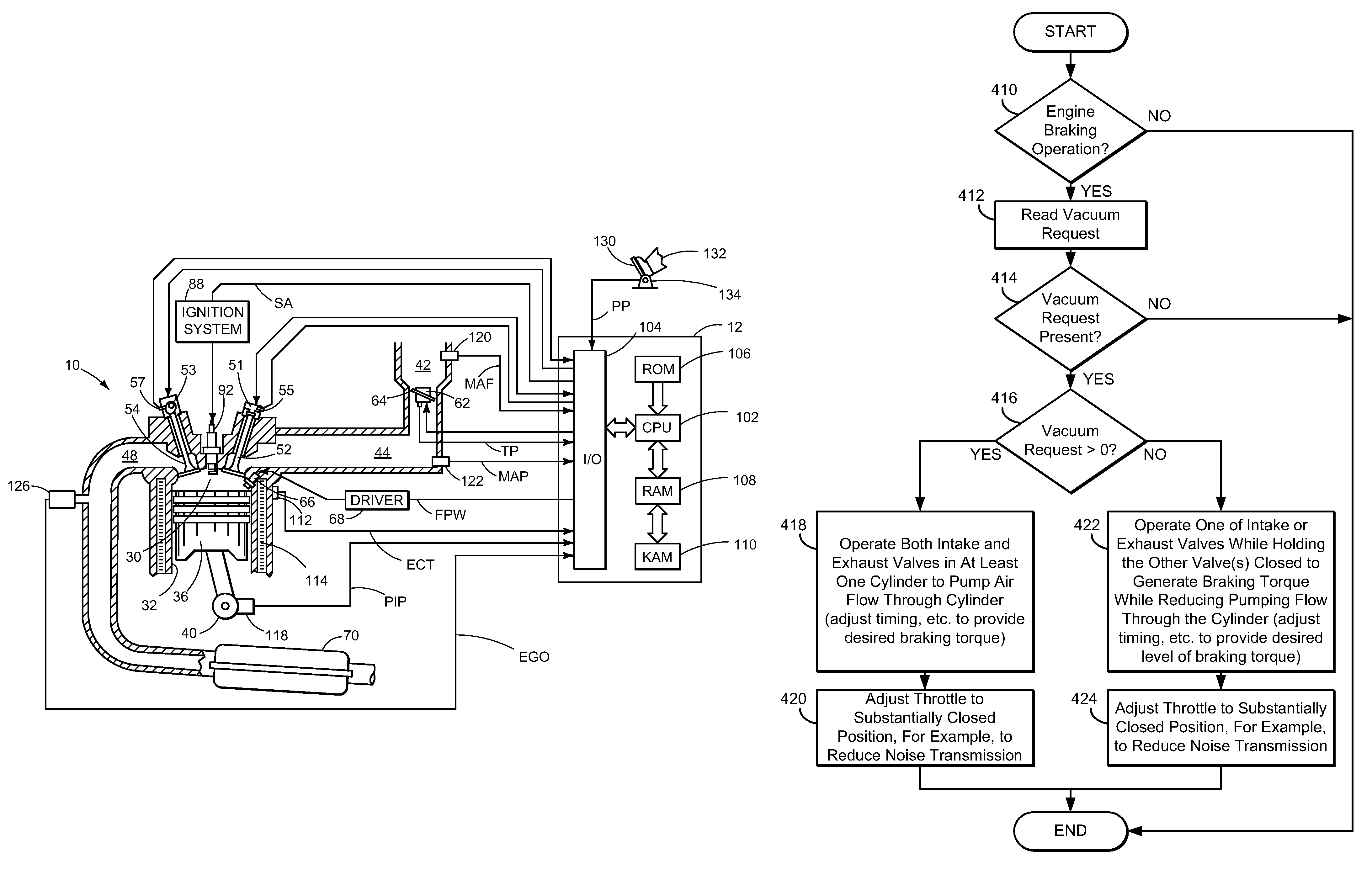
[0011]The present application describes various systems and methods for controlling vehicle operation including during deceleration conditions. In one particular example, the system provides engine cylinder expansion and / or compression braking in one or more cylinders to vary a level of engine braking during deceleration conditions and thereby improve vehicle response. Further, alternative valve opening timing, closing timing, and phase control are provided in response to varying vacuum levels and vacuum requests in the intake manifold, while also reducing flow of air through the engine to the exhaust.

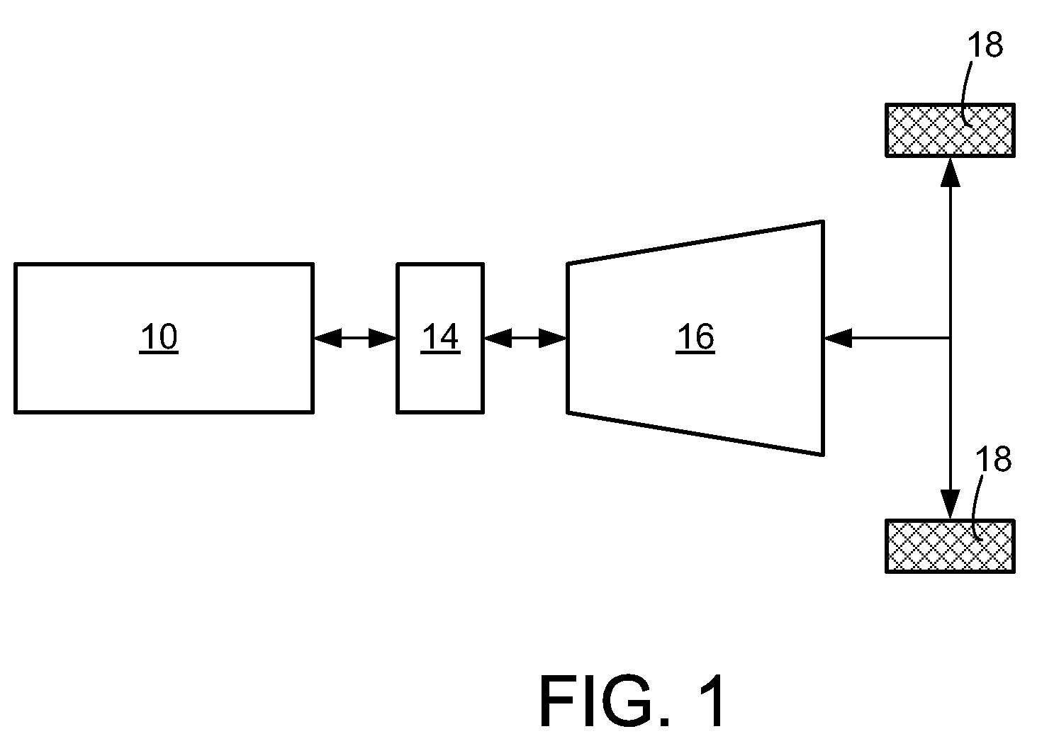
[0012]FIG. 1 schematically shows an example vehicle powertrain 20 including an internal combustion engine 10, a torque converter 14, a transmission 16 and one or more wheels 18 for transmitting propulsive force to the ground surface. In this example, torque may be selectively transmitted from the engine to one or more drive wheels via the torque converter and transmission. Similarly, t...


PUM


Abstract

A method of operating an engine for a vehicle having at least a first cylinder, the method comprising of operating the first cylinder to provide at least one of compression braking and expansion braking by holding one of an intake valve and an exhaust valve of the first cylinder closed while opening, closing, and opening the other of the intake valve and the exhaust valve during a cycle of the first cylinder and during a first vacuum level of an intake manifold upstream of the first cylinder; and operating the first cylinder to provide at least one of compression braking and expansion braking by operating both the intake valve and the exhaust valve of the first cylinder during a cycle of the first cylinder to allow at least some air to flow through the first cylinder during a second vacuum level of the intake manifold.

Description

BACKGROUND AND SUMMARY[0001]Some vehicles may include engines that are configured to shut-off the fueling and the ignition system of one or more of the cylinders during deceleration events also known as deceleration fuel shut-off (DFSO) in an effort to achieve improved fuel economy and reduced emissions. During these DFSO events, intake air not participating in combustion, may pass through the engine via one or more deactivated cylinders where it may reduce the effectiveness of a downstream exhaust catalyst via catalyst cooling and / or oxidant saturation.[0002]In one approach, an engine including intake and exhaust valves having electric valve actuation may close the intake valves of the deactivated cylinders to reduce airflow through the engine while the exhaust valves are controlled to modulate torque output. Similarly, engines having exhaust valves that are cam actuated may utilize a deactivation device for closing a sub-set of the exhaust valves. For example, the exhaust valves o...

Claims


Application Information

Patent Timeline
Patent Type & Authority Patents(United States)
IPC IPC(8): G06F19/00F01L9/04F01L1/34F02D13/04
CPCF02D13/04F02D41/0005F02D41/123Y02T10/42F02D2041/001F02D2250/41Y02T10/40
Inventor GIBSON, ALEXTRASK, NATEREED, DENNISKOLMANOVSKY, ILYA V.
Owner FORD GLOBAL TECH LLC
Why Eureka
Try Eureka