Variable-power optical system and imaging apparatus

a technology of applied in the field of variable-power optical system and imaging apparatus, can solve problems such as difficulty in achieving optical performance capable, and achieve the effects of wide angle of view, small size, and large aperture ratio

Inactive Publication Date: 2011-04-26
FUJI PHOTO OPTICAL CO LTD
View PDF13 Cites 7 Cited by
  • Summary
  • Abstract
  • Description
  • Claims
  • Application Information

AI Technical Summary

Benefits of technology

[0008]The invention has been made in order to solve the above-mentioned problems, and it is an object of the invention to provide a variable-power optical system that has a small size, a large aperture ratio, a wide angle of view, and a high optical performance capable of obtaining a high-quality image, and an imaging apparatus including the variable-power optical system.
[0011]In the variable-power optical system according to the above-mentioned aspect, since the first sub lens group including at least three negative meniscus lenses is arranged close to the object side, it is possible to achieve a wide angle of view while preventing distortion. In addition, since an aspheric lens is arranged closest to the object side lens in the second lens group, it is easy to correct spherical aberration that tends to increase with an increase in aperture ratio. Therefore, it is easy to achieve a large aperture ratio. Further, since the aspheric lens makes it easy to correct aberrations other than the spherical aberration, it is easy to obtain a high optical performance while reducing the size of an optical system. Furthermore, since the variable-power optical system according to the above-mentioned aspect satisfies Conditional expression 1, it is possible to maintain the power ratio of the first lens group to the entire optical system within an appropriate range. Therefore, it is possible to prevent the spherical aberration at a telephoto end while reducing the size of an optical system. As a result, it is possible to achieve an optical system that has a large aperture ratio and is capable of a high-quality image.
[0020]According to the variable-power optical system of the invention, a first lens group having a negative refractive power, an aperture diaphragm, and a second lens group having a positive refractive power are arranged in this order from the object side. The first lens group includes at least three negative meniscus lenses arranged close to the object side, and an aspheric lens is arranged closest to the object side in the second lens group. The structure of each lens group is appropriately set so as to satisfy Conditional expression 1. Therefore, it is possible to achieve an optical system that has a small size, a large aperture ratio, a wide angle of view, and a high optical performance capable of obtaining a high-quality image.
[0021]An imaging apparatus according to the invention includes the variable-power optical system according to the invention. Therefore, the imaging apparatus has a small size and a wide angle of view, and can capture a high-quality image even under low-brightness imaging conditions.

Problems solved by technology

However, in the optical system according to the related art, it is difficult to achieve an optical performance capable of corresponding to an increase in the number of pixels while maintaining a large aperture ratio required for the monitoring camera and obtaining a wide angle of view.

Method used


Image

  • Variable-power optical system and imaging apparatus
  • Variable-power optical system and imaging apparatus
  • Variable-power optical system and imaging apparatus

Examples


example 1

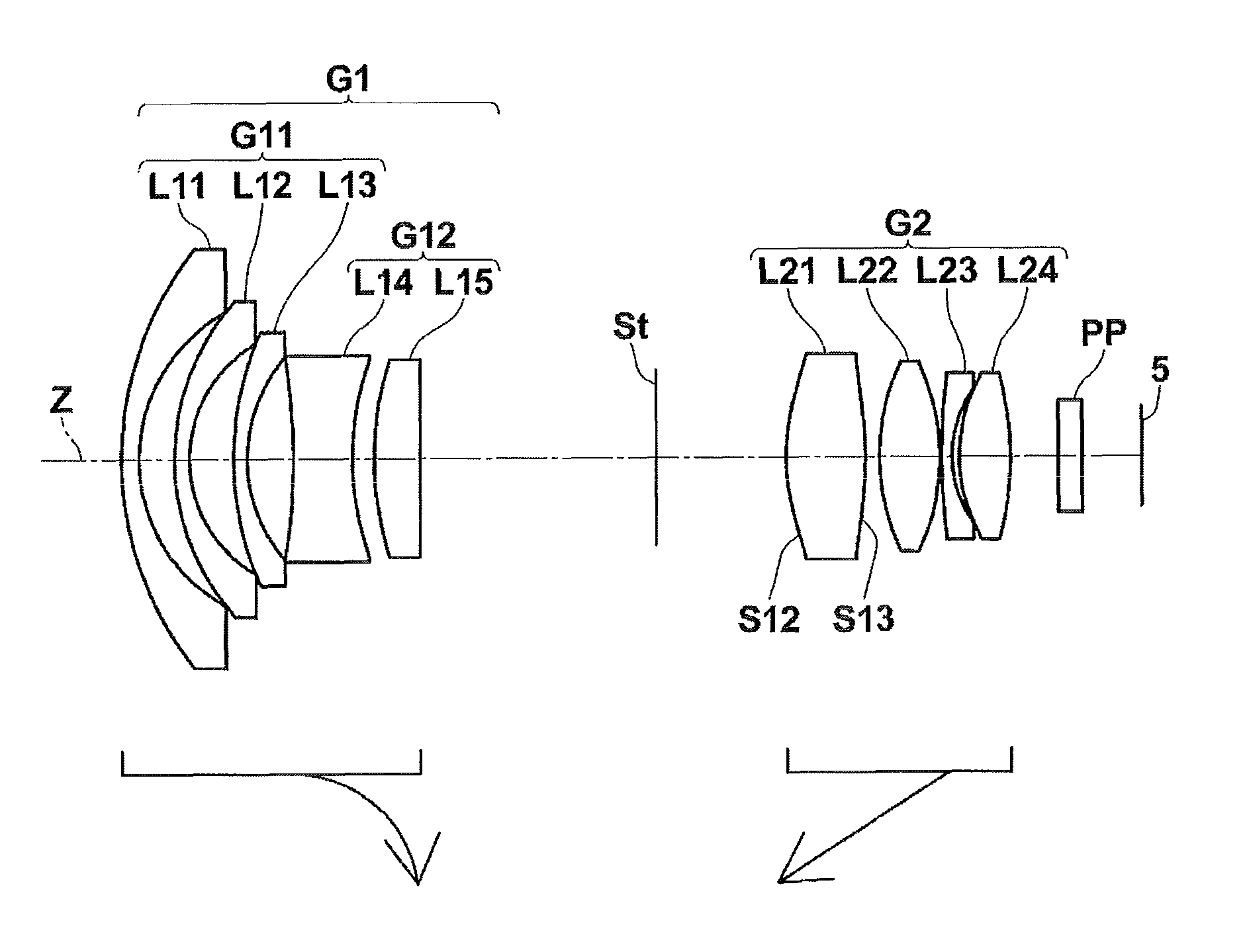
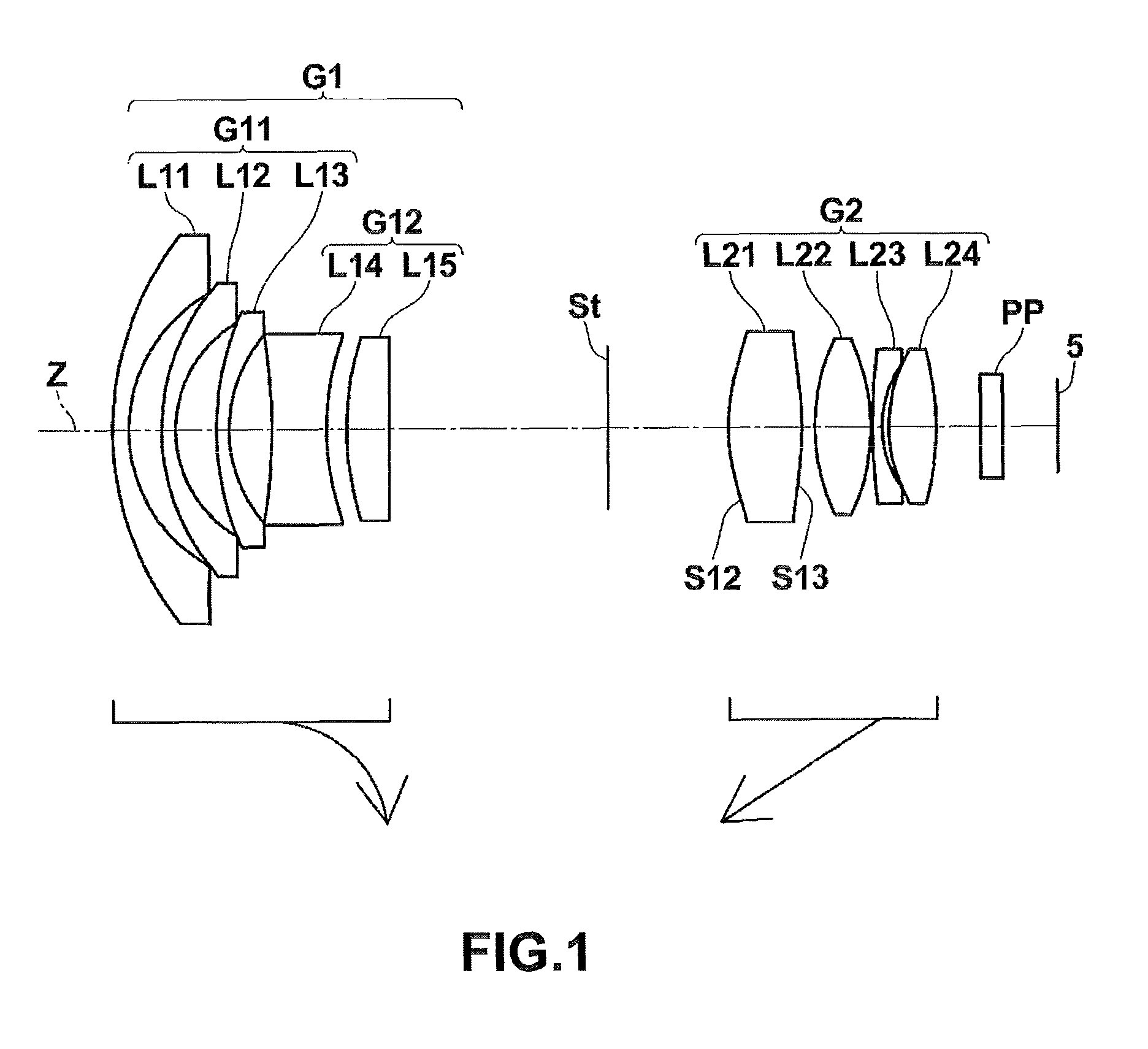
[0074]The cross-sectional view of lenses according to Example 1 is shown in FIG. 1. Specifically, a first lens group G1 of a variable-power optical system according to Example 1 includes meniscus-shaped negative lenses L11, L12, and L13 having convex surfaces facing the object side, a biconcave negative lens L14, and a plano-convex positive lens L15 having a convex surface facing the object side arranged in this order from the object side. The second lens group G2 includes a positive lens L21 having a biconvex shape in the vicinity of the optical axis, a biconvex positive lens L22, a meniscus-shaped negative lens L23 having a convex surface facing the object side, and a biconvex positive lens L24 arranged in this order from the object side. In the variable-power optical system according to Example 1, an object-side surface S12 and an image-side surface S13 of the lens L21 are aspheric surfaces. The position of the aperture stop St is fixed, but the diameter thereof is variable when ...

example 2

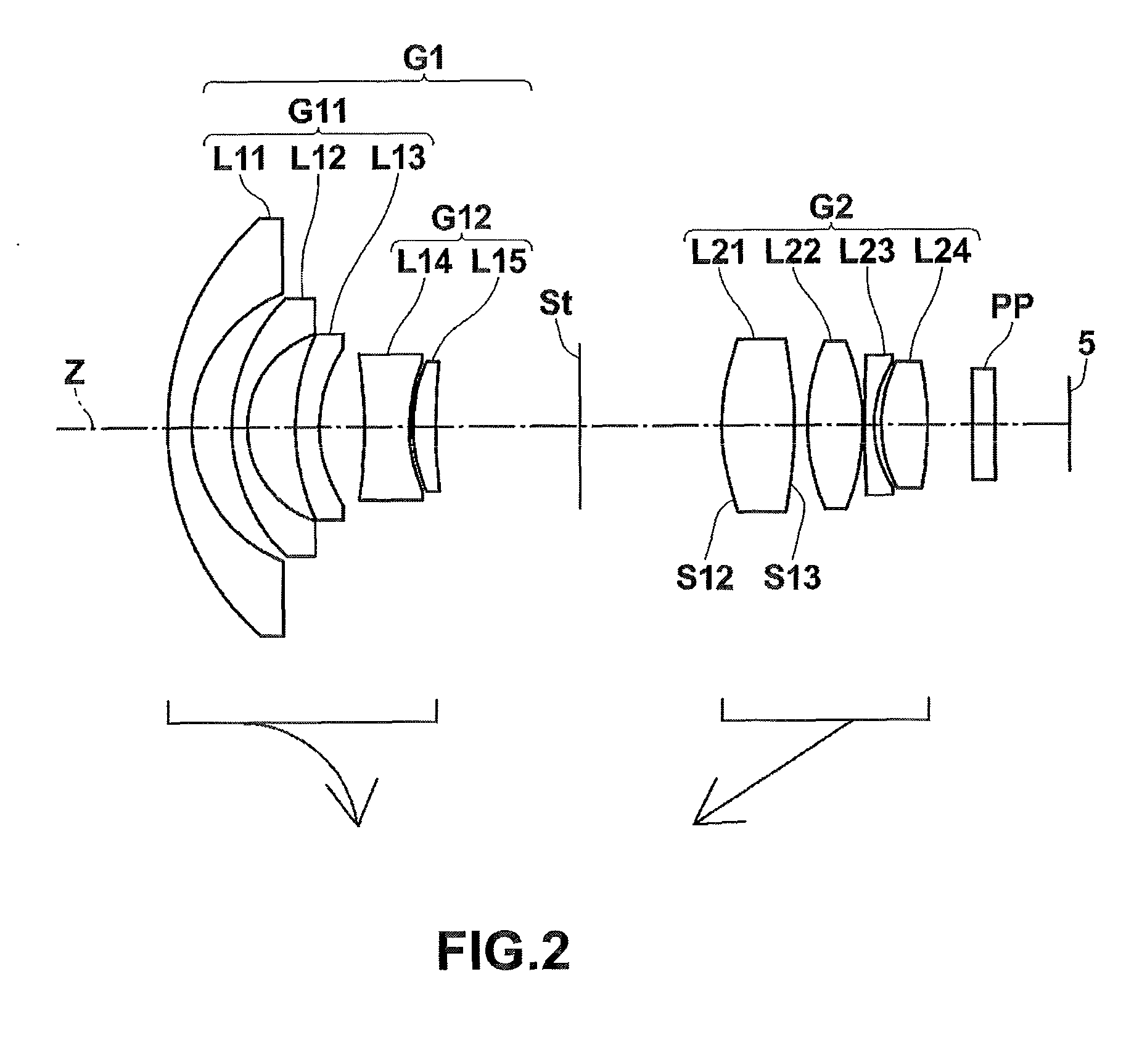
[0084]FIG. 2 is a cross-sectional view illustrating lenses according to Example 2. The basic lens structure of a variable-power optical system according to Example 2 is similar to that according to Example 1 except that a meniscus-shaped positive lens L15 having a convex surface facing the object side is used in Example 2 instead of the plano-convex lens L15 according to Example 1. In addition, in the variable-power optical system according to Example 2, an object-side surface S12 and an image-side surface of a lens L21 are aspheric surfaces.

[0085]Lens data of the variable-power optical system according to Example 2 is shown in Table 4, aspheric data thereof is shown in Table 5, and various data thereof is shown in Table 6.

[0086]

TABLE 4Example 2Lens dataSiRiDiNdjνdj 118.85441.671.8830040.8 29.68982.70 312.07471.071.8830040.8 46.61673.26 514.74791.641.8160046.6 69.56463.03 7−31.77503.051.7995242.2 811.31380.24 910.82961.551.9228618.91039.8198Variablespacing D111 (aperture stop)—Varia...

example 3

[0089]FIG. 3 is a cross-sectional view illustrating lenses according to Example 3. The basic lens structure of a variable-power optical system according to Example 3 is the same as that according to Example 2. In addition, in the variable-power optical system according to Example 3, an object-side surface S12 and an image-side surface S13 of a lens L21 are aspheric surfaces.

[0090]Lens data of the variable-power optical system according to Example 3 is shown in Table 7, aspheric data thereof is shown in Table 8, and various data thereof is shown in Table 9.

[0091]

TABLE 7Example 3Lens dataSiRiDiNdjνdj 121.89431.261.8348142.7 211.73352.92 314.64511.101.8830040.8 410.17642.84 516.46760.951.8830040.8 610.74454.17 7−35.78103.101.8040046.6 816.10171.81 921.68363.101.9228618.910604.6536Variablespacing D111 (aperture stop)—Variablespacing D212*10.79944.241.4970081.613*−93.96860.781410.00282.861.7291654.715−32.29760.321636.88480.822.0006925.5176.39900.671814.41201.581.6180063.419−18.2038Variab...


PUM


Abstract

The variable-power optical system is provided and includes a first lens group having a negative refractive power, a stop, and a second lens group having a positive refractive power, in order from an object side. The first lens group includes a first sub lens group having three negative meniscus lenses and a second sub lens group having a biconcave lens and a positive lens, in order from the object side. The second lens group includes a first positive lens arranged closest to the object side and having at least one aspheric surface and a second positive lens arranged immediately after the image side of the first positive lens. When the absolute value of the focal length of the first lens group is |f1| and the focal length of the entire system at a wide angle end is fw, the Conditional expression: 1.9<|f1| / fw<3.6 is satisfied.

Description

[0001]This application is based on and claims priority under 35 U.S.C §119 from Japanese Patent Application No. 2008-170863 filed on Jun. 30, 2008, the entire disclosure of which is herein incorporated by reference.BACKGROUND OF THE INVENTION[0002]1. Field of the Invention[0003]The present invention relates to a variable-power optical system used for, for example, a video camera or an electronic still camera and an imaging apparatus, and more particularly, to a variable-power optical system suitable to be used for a monitoring camera and an imaging apparatus including the variable-power optical system.[0004]2. Description of the Related Art[0005]Monitoring cameras have been used to operate unmanned facilities. In recent years, particularly, there is an increasing demand for monitoring cameras capable of changing power. A fast optical system having a large aperture ratio needs to be used as a variable-power optical system for the monitoring camera such that it can specify a subject e...

Claims


Application Information

Patent Timeline
Patent Type & Authority Patents(United States)
IPC IPC(8): G02B15/14
CPCG02B15/177G02B15/143503
Inventor TOMIOKA, UKYO
Owner FUJI PHOTO OPTICAL CO LTD
Why Eureka
Try Eureka