Method and system of motion artefact compensation in a subject

a technology of compensation and motion artefacts, applied in image data processing, instruments, character and pattern recognition, etc., can solve the problems of difficult to correct motion artefacts, and difficult to obtain data in the region of interest between successive time points at a fixed location, etc., to achieve the effect of maximising the detection of motion artefacts

Inactive Publication Date: 2011-04-26
APOLLO MEDICAL IMAGING TECH
View PDF8 Cites 5 Cited by
  • Summary
  • Abstract
  • Description
  • Claims
  • Application Information

AI Technical Summary

Benefits of technology

[0013]selecting a region of interest (ROI) covering an edge of the moving portion to maximise detection of motion artefacts;
[0022]enable the user to modify the ROI by covering an edge of the moving portion to maximise detection of motion artefacts;

Problems solved by technology

However, problems arise when obtaining the above-mentioned perfusion indices when the region of interest includes a tissue or organ that moves over time.
These motion artefacts make it difficult to obtain data in the region of interest between successive time points at a fixed location within the region of interest due to the movement of the tissue or organ in the region of interest.
Due to local tissue stretching and non-uniform distortion, these motion artefacts are not easily correctable using conventional image registration methods for the brain.
Breath holding, for up to 20 seconds, is the common method during scanning to minimize respiratory motion artefact, however it is not effective for a typical dynamic scan which takes more than 40 seconds.
Other methods of minimizing these motion artefacts are by cardiac and / or respiratory gating during a scan subject to limitations of the hardware used.

Method used


Image

  • Method and system of motion artefact compensation in a subject
  • Method and system of motion artefact compensation in a subject
  • Method and system of motion artefact compensation in a subject

Examples


Embodiment Construction

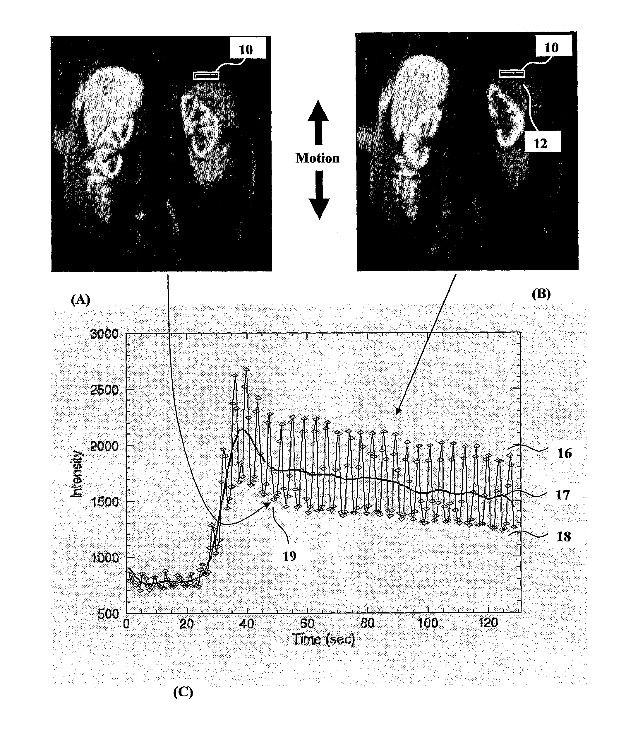
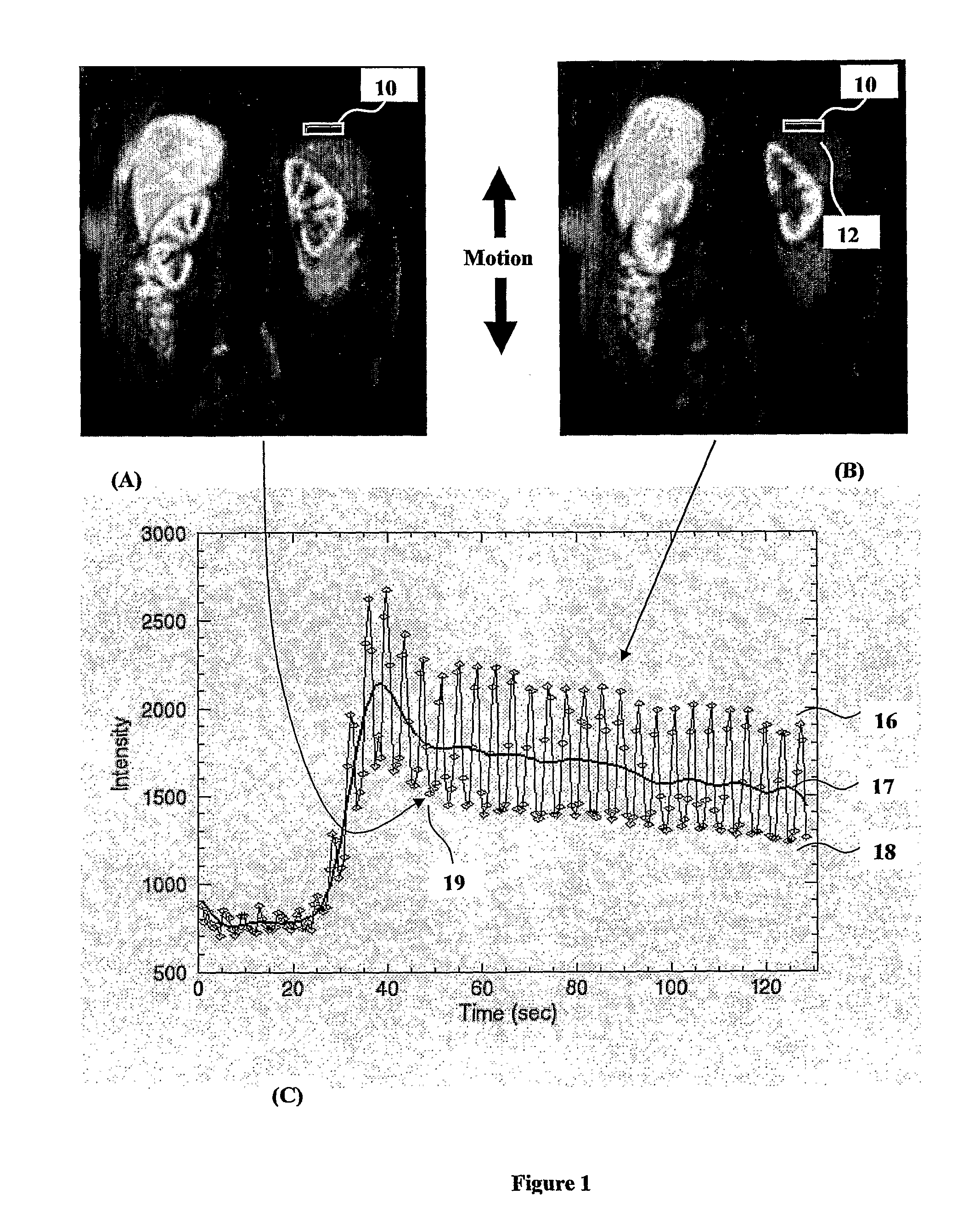
[0049]In FIG. 1A there is shown a region of interest 10 over a portion of a subject, in this case an organ from a patient and in particular is located in a coronal plane on the upper edge of the organ 12. As the patient breathes the movement of the organ is mostly in an up and down motion which yields a minimum area of the organ in FIG. 1A which is within the ROI 10 at one time point and a maximum area of the organ in FIG. 1B within the same ROI 10 at another time point.

[0050]FIG. 1C shows a plot against time of the fluctuation of average intensity of ROI 10 due to the up and down motion of the organ 12. The minimum signal intensity data points in FIG. 1A and data points representative of when the organ is in a similar position to that shown in FIG. 1A is represented by the low boundary profile 18. The maximum signal intensity data points in FIG. 1B and data points representative of when the organ is in a similar position to that shown in FIG. 1B is shown by the high boundary profil...


PUM


Abstract

A method of compensating for motion artefact of a portion of a subject, wherein signal intensity data representing movement of the portion of the subject is recorded and plotted on a display means. The method includes selecting a region of interest (ROI) covering an edge of the moving portion, calculating and plotting data points representing the average signal intensity of the selected ROI at specific time instances, producing a smoothed curve representing the mean of the plotted data points. The method further includes measuring the difference between the plotted data points and the smoothed curve at particular time instances to produce a difference curve, detecting a set of critical points on the difference curve, and interpolating the detected set of critical points to form a curve of equal time intervals for subsequent processing.

Description

FIELD OF THE INVENTION[0001]This invention relates to a method and system of compensating for motion artefacts in a subject, and more particularly relates to a method and system of compensating for motion artefacts in a region of interest of a subject in order to obtain improved data in blood perfusion measurements.BACKGROUND TO THE INVENTION[0002]The process of measuring blood flow within a body of a subject non-invasively is useful in diagnosing and treating the subject. This is particularly the case where a part of a subject or patient, such as a tissue or organ, suffers from diseases due, for example, to cancer or malfunction. Determining perfusion indices including the blood flow through such a tissue or organ can provide important information to a physician in order to determine an appropriate treatment regime for the patient.[0003]Existing systems pertaining to blood flow information have been disclosed. In general, the systems involve a contrast agent which is delivered as a...

Claims


Application Information

Patent Timeline
Patent Type & Authority Patents(United States)
IPC IPC(8): G06K9/40G06K9/00
CPCG06T7/20G06T5/50A61B6/507
Inventor YANG, QING
Owner APOLLO MEDICAL IMAGING TECH
Why Eureka
Try Eureka