
Device and method for optical measurement of a target

a target and optical measurement technology, applied in the direction of optical radiation measurement, instruments, spectrophotometry/monochromators, etc., can solve the problems of insufficient information on sulphur content, large instruments, and high cost, and achieve low cost, low cost, and the effect of small power consumption of measurement equipmen

Inactive Publication Date: 2016-09-01
TEKNOLOGIAN TUTKIMUSKESKUS VTT
View PDF4 Cites 3 Cited by
  • Summary
  • Abstract
  • Description
  • Claims
  • Application Information

AI Technical Summary

Benefits of technology

The present invention is a measurement device that has several technical effects. It provides a high signal-to-noise ratio, which is very useful for measuring chemical elements. The device is relatively efficient, as it uses a laser diode and a point detector to measure all available radiation. The device is also cost-effective as it uses commercially available components and does not require high-end optics or power sources. It is small in size and can be made robust, as it does not require sensitive components. Additionally, it can measure NIR wavelengths without being affected by background fluorescence.

Problems solved by technology

There are some disadvantages related to using prior art technology for monitoring material contents in mass applications, such as the monitoring contents of sulphur.
As a consequence, those methods do not provide adequate information on sulphur contents.
Prior art Raman spectrometers are suitable for laboratories, but there are some problems in using them in mass applications like the measurement of sulphur from fuel.
However, the instrument is very large-sized and expensive, and it is therefore not suitable for mass applications.
Due to the low intensity of the Raman scattered signal and high spectral resolution of the spectrometer the measurement also tends to take a long time in order to achieve a sufficient signal-to-noise ratio.

Method used


Image

  • Device and method for optical measurement of a target
  • Device and method for optical measurement of a target
  • Device and method for optical measurement of a target

Examples


Embodiment Construction

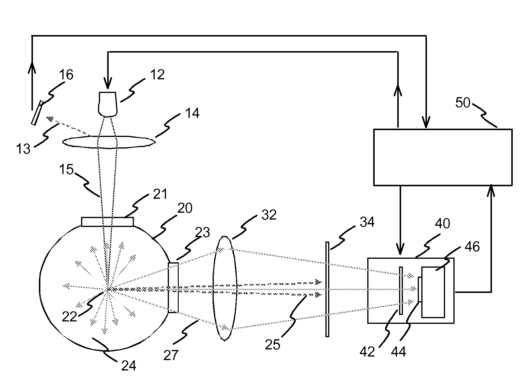
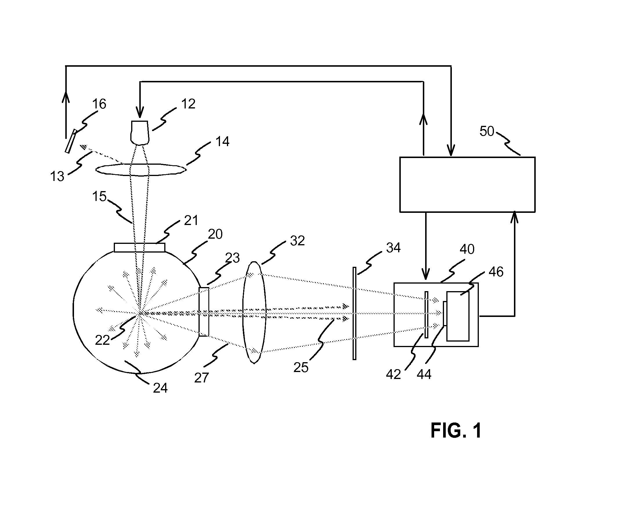
[0039]FIG. 1 illustrates an exemplary measurement device according to the invention. The device has a laser radiation source 12. The radiation source is preferably a laser diode. The output optical power can be e.g. within range 5-50 W, such as 20 W. The radiation source is controlled with control means, such as a microcontroller 50. The radiation beam 15 of the radiation source is focused into a measurement point 22 with a lens 14. There may also be a filter (not shown in FIG. 1) within the path of the activation radiation beam. A filter can be used for blocking possible disturbing radiation on other wavelengths from reaching the measurement space. The device may also have a separate photo detector 16 for monitoring the intensity of the radiation provided by the radiation source. The photo detector 16 may measure radiation 13 reflected from the lens 14, for example. The measurement of the radiation output can be used as a feedback by the control means 50 in controlling the laser di...


PUM


Abstract

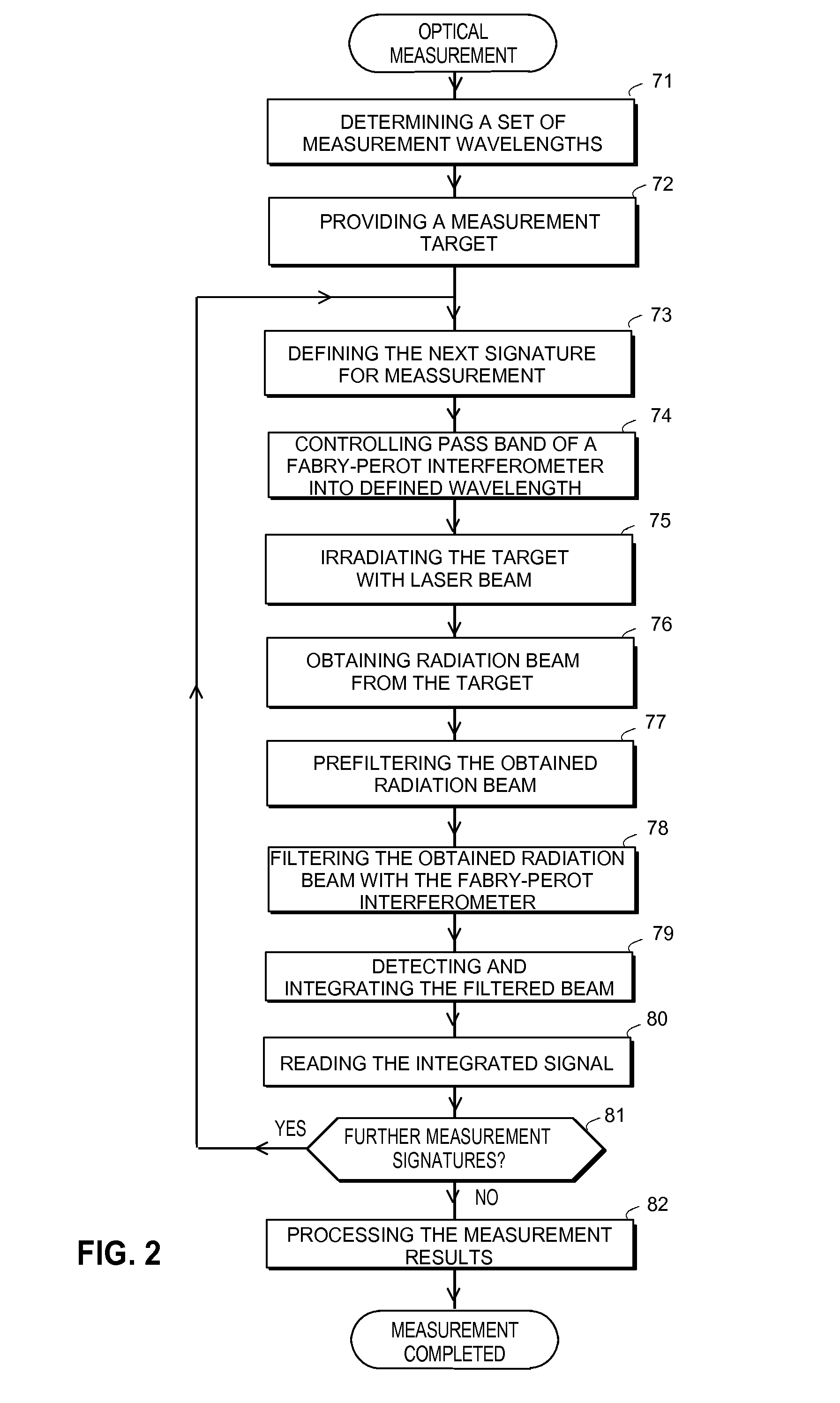
A device and a method for optical measurement of a target, wherein the target is irradiated with radiation beam (15) and a measurement beam (27) is received from the target and detected. Commonly used absorbance, reflectance and fluorescence measurements do not provide adequate information in e.g. measuring small contents of sulphur compounds. The present solution provides a new Raman spectrometer which is suitable for mass applications. A target is activated with pulses of a laser diode (12). The Raman signatures are measured and integrated successively with a point detector (44). A Fabry-Perot interferometer (42) on the measurement path is successively controlled into corresponding pass bands. While high spectral resolution or range is not required it is possible to use small-sized and low cost components.

Description

TECHNICAL FIELD[0001]The invention relates to a device and a method for optical measurement of a target, wherein the target is irradiated with radiation beam and a measurement beam is received from the target and detected.BACKGROUND TECHNOLOGY[0002]Optical measurement systems are used for e.g. analysing properties or material contents of a target. The most common optical measurement devices are based on light absorbance / reflection of a target or fluorescence of a target. Such measurements are needed in laboratories and industry, for example. However, there is also a growing need for continuous monitoring of material contents in mass applications, i.e. in applications where a large number of devices are needed and low cost of the devices is important. One such application is monitoring the contents of sulphur in various processes, and especially monitoring contents of sulphur compounds and additives in fuel of a vehicle.[0003]There are some disadvantages related to using prior art te...

Claims


Application Information

Patent Timeline
IPC IPC(8): G01J3/26
CPCG01J3/26G01J3/44G01N21/65G02B5/28G02B26/00
Inventor ANTILA, JARKKOTENHUNEN, JUSSI
Owner TEKNOLOGIAN TUTKIMUSKESKUS VTT
Learn More