
Partitioning code in program code conversion

a program code and code technology, applied in the field of computer and computer software, can solve the problems of not being able to evolve in performance or market reach, unable to find and delete the target code which corresponds to a given subject address, and difficulty in modifying code that is self-modifying, etc., and achieve the effect of limiting the amount of target cod

Active Publication Date: 2011-04-26
INT BUSINESS MASCH CORP
View PDF11 Cites 8 Cited by
  • Summary
  • Abstract
  • Description
  • Claims
  • Application Information

AI Technical Summary

Benefits of technology

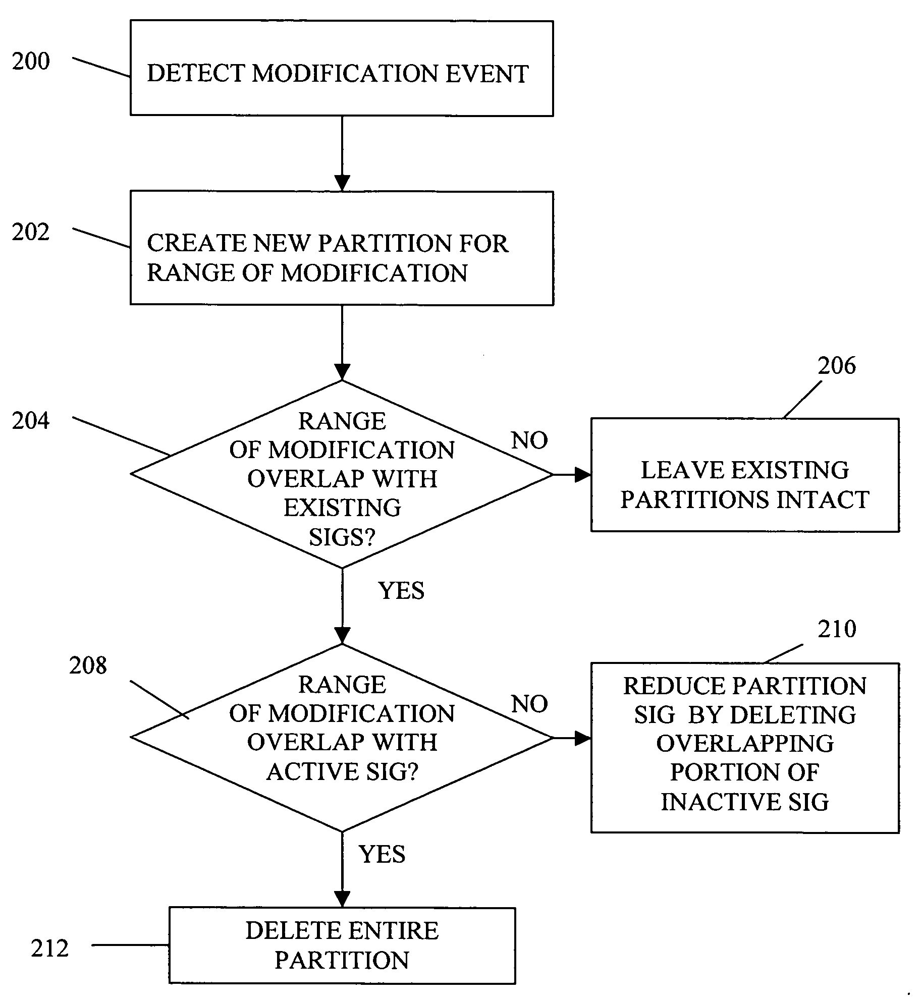
The invention is about a technique to optimize the conversion of program code, especially when using a run-time translator that translates code into target code. The technique involves dividing the code space into partitions, each containing a distinct set of basic blocks and their corresponding target code. This helps to reduce the amount of target code that needs to be retranslated in response to self-modifying code. The technique also allows for thread-safe code modification in multithreaded programs that involve self-modifying code. Overall, this technique improves the efficiency and speed of code conversion.

Problems solved by technology

One also finds dominant CPU architectures that are locked in time to their ISA, and cannot evolve in performance or market reach.
During program code conversion of a subject program designed for a subject architecture to a target program executable by a target architecture, a problem arises with respect to code that is self-modifying.
One of the main problems presented by self-modifying code to dynamic translators is that the subject code that was modified may correspond to target code which has already been translated.
In dynamic translators, finding and deleting the target code which corresponds to a given subject address is difficult and sometimes not even possible.
In these situations, if the subject program modifies its own code at certain subject address, the translator has no way to identify which respective translated target code to invalidate.

Method used


Image

  • Partitioning code in program code conversion
  • Partitioning code in program code conversion
  • Partitioning code in program code conversion

Examples


Embodiment Construction

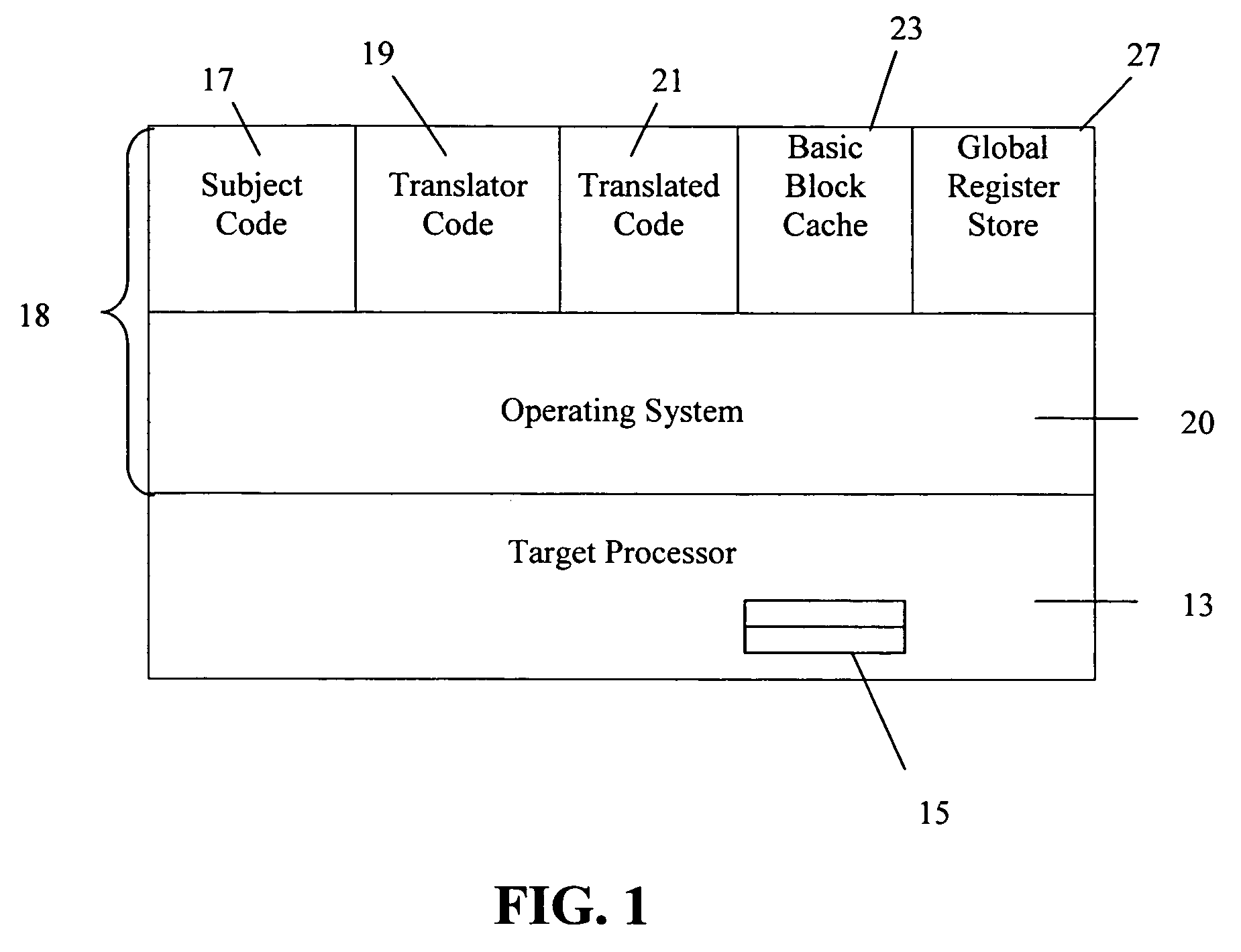
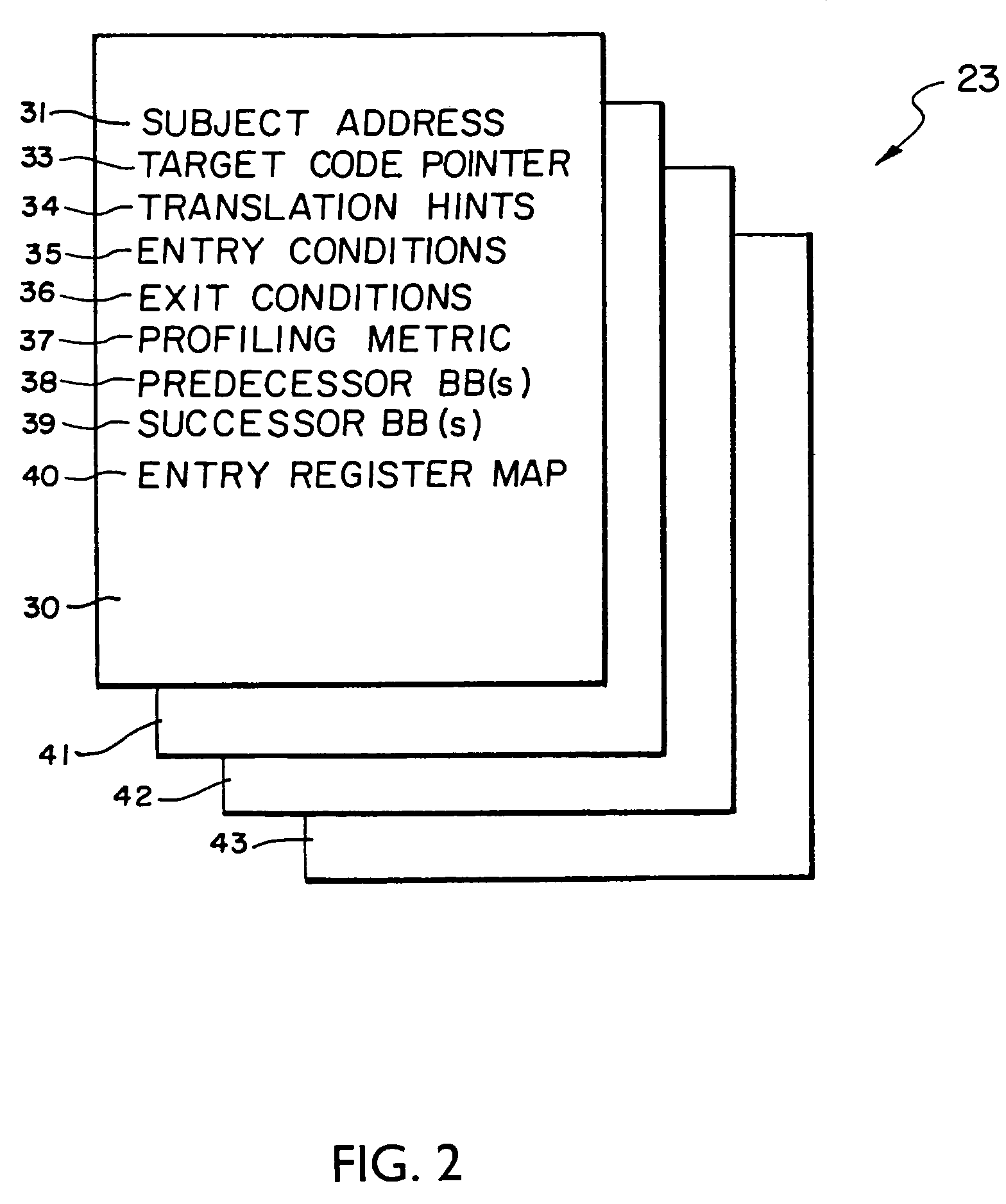
[0023]Illustrative apparatus for implementing various novel features discussed below is shown in FIG. 1. FIG. 1 illustrates a target processor 13 including target registers 15 together with memory 18 storing a number of software components 19, 20, 21, where such memory 18 further provides a working storage for a basic block cache 23, a global register store 27, and the subject code 17 to be translated. The software components include an operating system 20, the translator code 19, and translated code 21. The translator code 19 may function, for example, as an emulator translating subject code of one ISA into translated code of another ISA or as an accelerator for translating subject code into translated code, each of the same ISA.

[0024]The translator 19, i.e., the compiled version of the source code implementing the translator, and the translated code 21, i.e., the translation of the subject code 17 produced by the translator 19, run in conjunction with the operating system 20 such ...


PUM


Abstract

A partitioning technique utilized by a translator to divide the subject code space into regions, referred to hereafter as partitions, where each partition contains a distinct set of basic blocks of subject code and corresponding target code. The partitioning technique divides the translator's representation of subject code and subject code translations into non-overlapping regions of subject memory. In this manner, when the subject program modifies subject code, only those partitions actually affected by the self-modifying code need be discarded and all translations in unaffected partitions can be kept. This partitioning technique is advantageous in limiting the amount of target code that must be retranslated in response to self-modifying code operation. In another process, the partitioning technique allows multithreaded subject programs that also involve self-modifying code to perform code modification in a thread-safe manner.

Description

CROSS REFERENCE TO RELATED APPLICATIONS[0001]This application claims priority to GB 0316532.1, filed Jul. 15, 2003, and to GB 0328121.9, filed Dec. 9, 2003.BACKGROUND[0002]1. Technical Field[0003]The subject invention relates generally to the field of computers and computer software and, more particularly, to program code conversion methods and apparatus useful, for example, in code translators, emulators and accelerators.[0004]2. Description of Related Art[0005]In both embedded and non-embedded CPU's, one finds predominant Instruction Set Architectures (ISAs) for which large bodies of software exist that could be “accelerated” for performance, or “translated” to a myriad of capable processors that could present better cost / performance benefits, provided that they could transparently access the relevant software. One also finds dominant CPU architectures that are locked in time to their ISA, and cannot evolve in performance or market reach. Such architectures would benefit from “Syn...

Claims


Application Information

Patent Timeline
Patent Type & Authority Patents(United States)
IPC IPC(8): G06F9/45G06F9/445
CPCG06F9/45516G06F8/36
Inventor BROWN, ALEXKNOWLES, PAUL THOMASNORTH, GERAINT
Owner INT BUSINESS MASCH CORP
Learn More