Silicon breast implant injector for augmentation mammaplasty

a breast implant and injector technology, applied in the field of silicone breast implant injector for augmentation mammaplasty, to achieve the effects of facilitating augmentation mammaplasty, enhancing implant safety, and facilitating augmentation mammaplasty

Active Publication Date: 2011-05-03
TSAO SU BEN
View PDF25 Cites 10 Cited by
  • Summary
  • Abstract
  • Description
  • Claims
  • Application Information

AI Technical Summary

Benefits of technology

[0015]Therefore the primary object of the present invention is to provide a silicon breast implant injector that can easily and safely insert a silicon breast implant into the submammary pocket to facilitate augmentation mammaplasty and enhance implant safety.
[0016]The silicon breast implant injector aims to facilitate the silicon breast implant to be quickly passed into the submammary pocket to augment the breast. The injector can shorten surgery time, reduce incision wound damage and scar formation caused by forcefully squeezing the silicon breast implant through a small incision and decreases the finger hurting of the surgeon. Leakage or disruption of the silicon breast implant after surgery also is less likely to occur. The implant injector of the invention includes a hollow tube and a plunger.
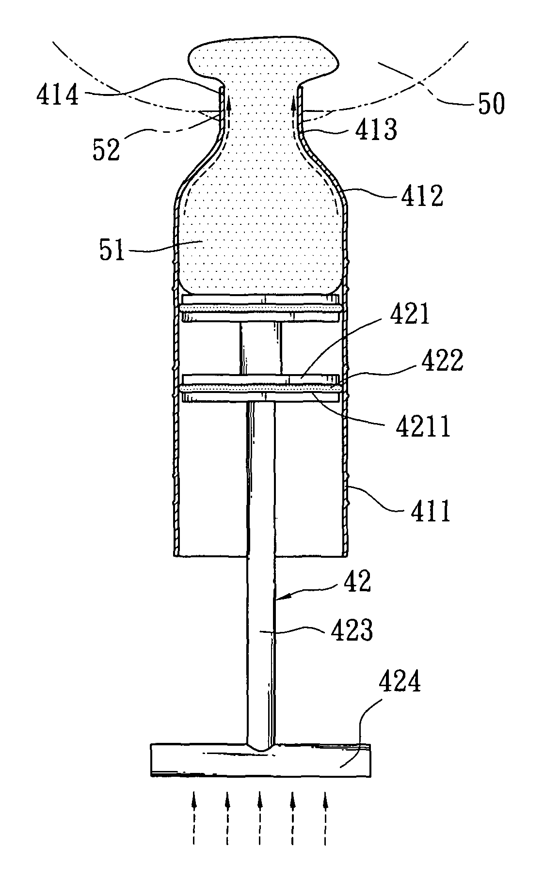
[0019]The first arched barrel and the second arched barrel form a smooth connection to reduce push resistance. When in use, a silicon breast implant is disposed in the barrel and pushed by the plunger through the ejection opening. The silicon breast implant is coated with a lubricating fluid non-irritating to human body, thus can be easily and safely pushed and passed into the sub-mammary pocket. As a result, augmentation mammaplasty can be performed rapidly and safely.
[0020]By means of the construction set forth above, the invention can provide the following effects and benefits:
[0021]1. The implant injector of the invention has the first arched barrel tapered at one end to connect an inverse second arched barrel to form a smooth junction. Hence the silicon breast implant disposed in the barrel and pushed by the plunger can be quickly and safely ejected through the ejection opening and the wound incision into the submammary pocket to augment the breast.
[0022]2. The smooth junction of the first arched barrel and the inverse second arched barrel at one end of the barrel can reduce resistance. Hence during inserting the silicon breast implant coated with non-irritating lubricating fluid, disposed through one end of the first arched barrel, the silicon breast implant can be pushed forwards easily by the plunger through the ejection opening at the front end and the wound incision into the submammary pocket to augment the breast.

Problems solved by technology

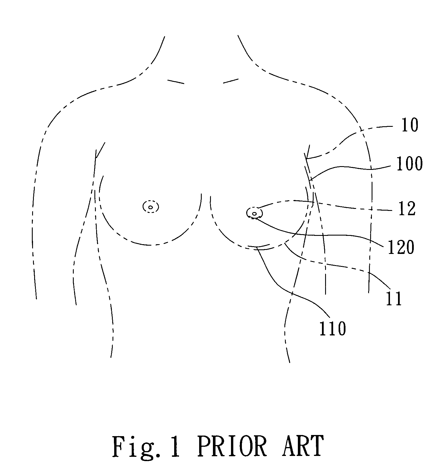
1. The silicon breast implant is quite bulky and difficult to be inserted manually through the incision 100, 110 or 120. The tissues around the incision 100, 110 and 120 easily become rotten and incision enlarged. Scar is hence easily formed and noticeable after operation.
2. The silicon breast implant is inserted forcefully by fingers through the incision 100, 110 or 120, and is possibly damaged. After a period of time the silicon breast implant could be leaking or disrupted to make the breast hardened or deformed, and result in operation failure.
3. By pushing forcefully the silicon breast implant through the incision 100, 110 or 120 with fingers surgeon's fingers could be hurt.
4. To implant the silicon breast implant through the incision 100, 110 or 120 by pushing with fingers, operation time is longer and results in unfavorable condition to patients.
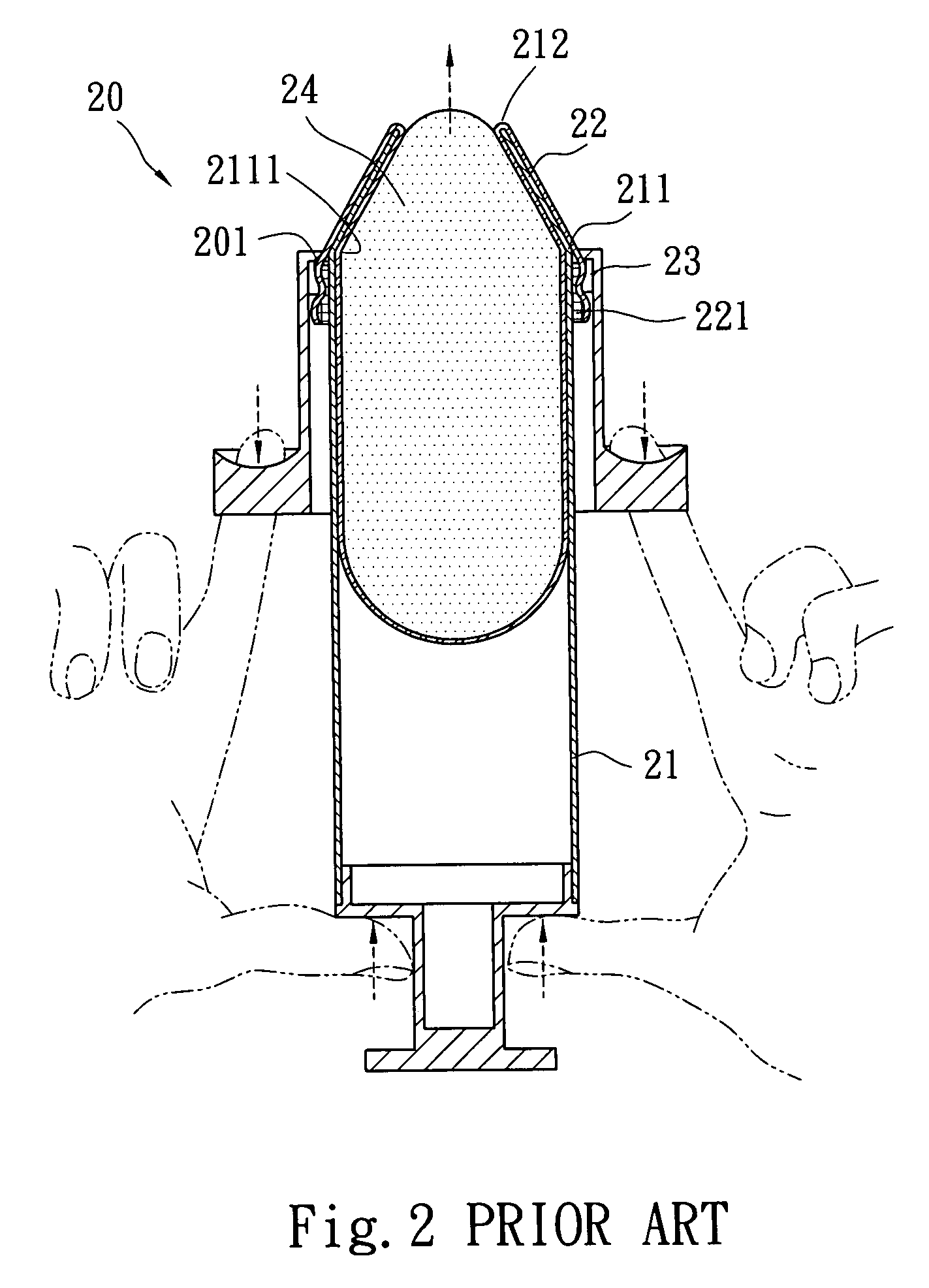
1. The conical opening 212 can only be in inserted in a very shallow location at the incision site rather than in a proper depth. Unless the incision is made larger for the conical opening insertion deeper, the breast implant 24 cannot be inserted deeply inside from the incision and into the submammary pocket, thus the implanted breast implant 24 will easily loosens off after insertion. So that it does not provide much benefits to the operation.
2. The conical opening 212 and the one end 211 of the tube 21 are joined at a location where an unsmooth angular corner 2111 is formed. The angular corner 2111 creates a greater friction to the breast implant 24 and makes pushing out of the breast implant 24 through conical opening 212 difficult.
3. During pushing of the breast implant 24 the outer side of the bag 22 has to be pulled downwards toward the nozzle 201 by the injector 20 (referring to the arrow shown in FIG. 2). A great friction and resistance takes place while the bag 22 is located at the conical opening 212. Adding the resistance caused by the angular corner 2111, the bag 22 could be broken, and pushing out of the breast implant 24 is even more difficult.
1. It has a guiding rod 31 which is inserted into the injection barrel 30 through a tail end and has a front end extended outside an injection opening 32 where twelve pieces of flaps 33 are being extended first. As the twelve flaps 33 are formed by an injection process, they tend to stick together. Hence they have to be extended first by the front of the guiding rod 31 before they are inserted in the incision of a patient to allow the opening 32 to be disposed inside the incision. Then a plunger 35 with a hard head 351 is pushed forwards through a rear end of the injection barrel 30 as shown in FIG. 4A to inject a breast implant 34 through the opening 32 into a inner side of the breast of the patient for positioning. While the breast implant 34 is pushed and passes through the opening 32, the twelve flaps 33 are pushed by the breast prosthesis 34 to extend outward and form gaps among them. The breast implant 34 thus tends to be wedged in these gaps and damaged during it's being pushed to pass through the opening 32 (referring to FIG. 4B).
2. The injection barrel 30 gradually forms a tapered portion at the bottom of the opening 32 adjacent to the twelve flaps 33. Unsmooth angular corners 301 and 302 are formed at the junction that become obstacles during pushing of the breast implant 34 by the hard head 351 of the plunger 35 in the injection barrel 30. The breast implant 34 cannot be moved smoothly and clogging could occur. When the breast implant 34 reaches the angular corner 301 at the top end of the barrel and the bottom end of the angular corner 302, a greater resistance force is formed. As a result moving of the breast implant 34 is difficult.
3. Because of the inadequate design of twelve flaps 33, an extra element of the guiding rod 31 has to be provided. More unnecessary surgical procedure is needed because of this situation.

Method used


Image

  • Silicon breast implant injector for augmentation mammaplasty
  • Silicon breast implant injector for augmentation mammaplasty
  • Silicon breast implant injector for augmentation mammaplasty

Examples


Embodiment Construction

[0036]Please refer to FIGS. 5 and 6 for an embodiment of a silicon breast implant injector 40 of the invention, It aims to facilitate the silicon breast implant 51 to be quickly and safely inserted at submammary pocket without being damaged, and enhance implant safety. The silicon breast implant injector 40 includes a hollow tube 41 and a plunger 42.

[0037]The hollow tube 41 has a cylindrical barrel 411. The barrel 411 has one end tapered to form a first arched barrel 412 to connect an inverse second arched barrel 413. The second arched barrel 413 is connected to an ejection opening 414 of the same diameter but formed into a short length tube.

[0038]The plunger 42 has at least one flattened and circular thrust disk 421 at one end formed at a diameter slightly smaller than the inner diameter of the barrel 411. The thrust disk 421 has a groove 4211 formed on the perimeter to be wedged by a pliable padding ring 422 that is formed at a diameter substantially equal to the inner diameter of...


PUM


Abstract

A silicon breast implant injector for augmentation mammaplasty which includes a hollow tube and a plunger. The hollow tube has a barrel which has one end tapered to form a first arched barrel connecting to an inverse second arched barrel which in turn is connected to an ejection opening formed at the same diameter as the second arched barrel but into a short inflexible length tube. The plunger can push a silicon breast implant s held in the hollow tube through an incision into patient's submammary pocket. Coupled with a smooth connection between the first arched barrel and the second arched barrel, push resistance can be reduced, and thus can smoothly, quickly, easily and safely move the silicon breast implant into the submammary pocket.

Description

FIELD OF THE INVENTION[0001]The present invention relates to a silicon breast implant injector for augmentation mammaplasty, particularly to an injector to easily and safely insert a silicon breast implant into the submammary pocket to facilitate augmentation mammaplasty and enhance implant safety.BACKGROUND OF THE INVENTION[0002]Conventional silicon breast implant augmentation mammaplasty (referring to FIG. 1) usually is performed by slitting an incision 100 at the armpit 10, or an incision 110 below the breast 11, or an incision 120 below the areola 12, then inserting a breast implant through the incision 100, 110 or 120 below the breast 11 to augment the breast. During such an operation some problems and difficulties occur, notably:[0003]1. The silicon breast implant is quite bulky and difficult to be inserted manually through the incision 100, 110 or 120. The tissues around the incision 100, 110 and 120 easily become rotten and incision enlarged. Scar is hence easily formed and ...

Claims


Application Information

Patent Timeline
Patent Type & Authority Patents(United States)
IPC IPC(8): A61M5/315A61M31/00A61M5/00A61F2/12
CPCA61F2/12A61B17/3468
Inventor TSAO, SU-BEN
Owner TSAO SU BEN
Why Eureka
Try Eureka