Device and method for automatically starting a milking process

Active Publication Date: 2011-05-10
GEA FARM TECH
View PDF13 Cites 2 Cited by
  • Summary
  • Abstract
  • Description
  • Claims
  • Application Information

AI Technical Summary

Benefits of technology

[0039]It is a significant advantage of the present invention as regards the automatic start function and also the rapid ventilation function that existing installations can readily be retrofitted. Existing installations can be retrofitted through replacing a few components wherein the cylinder sleeve of the milking unit cylinder can generally remain while the piston, the sensor element and the like are replaced. Retrofitting is possible due to the small structural volume.
[0040]In all configurations of the milking unit cylinder with rapid ventilation, said rapid ventilation is preferably controlled by means of a rapid ventilation or pilot valve at the cylinder. A rapid ventilation valve allows to control the valve through relatively small control air cross-sections wherein a large air cross-section is opened for ventilation. The valve is preferably positively actuated which allows reliable switching and makes the switching point independent of the current pressure ratios.
[0041]It is preferably provided to control the membrane or the rapid ventilation through a control port with separate control air. The control port preferably leads into a control volume that is completely closed versus the interior of the milking cylinder such that there is no flow connection between them and no air will be exchanged between the air for operating the milking unit cylinder and the control air for the rapid ventilation. It is advantageous to use the control air for the rapid ventilation not for aeration or ventilation but only for valve control: this will allow reliable switching. Otherwise certain intermediate valve positions might cause exchanges between inlet air and outlet air. For example when the evacuation port is already slightly opened while the inlet port is still slightly open, both could be short-circuited so as to result in an indeterminate intermediate position where no autonomous opening or closing will occur. To avoid such intermediate positions, a fast vacuum build-up or air inlet is therefore required which is, however, not always desired in particular for vacuum build-up.
[0042]In the interior of the rapid ventilation valve the membrane is in particular applied. It is also conceivable to use a rapid ventilation valve with piston control instead of membrane control. To this purpose the piston is guided in an intake. When the piston is in a first (end) position, the rapid ventilation is for example operative and in a second (end) position the rapid ventilation is locked. The piston may be configured to be brought into the first position by control air at atmospheric pressure and to be brought into the second position by a vacuum on the control side. The dimensions of the piston and intake are preferably chosen such that leakage loss will be low and friction loss in piston movement will be low wherein the surfaces are configured such that the forces acting on the piston are sufficient for the respective application.
[0043]It is a disadvantage of a rapid ventilation valve with piston control that due to contamination, friction of the piston in the intake can rise considerably until control is no longer possible. It is another disadvantage that the switching point depends on the current pressure conditions. One advantage of a membrane is that no air whatever is exchanged and the function of a membrane is considerably less susceptible to contamination.
[0044]A biasing means is preferably provided for biasing the membrane in the direction of a closed position. Said membrane can preferably be displaced against the force of the biasing means into at least one ventilation position. In the ventilation position, air can be let in through the rapid ventilation aperture.

Problems solved by technology

Such oscillating motion of the cylinder and the milking unit occurs within the operating range of the milker who may be considerably irritated.
It is a disadvantage in the known prior art that the removal cylinder must be considerably pivoted for starting.
In addition the removal cylinder swings out after the end of the milking process which may inhibit the work of the milker.

Method used


Image

  • Device and method for automatically starting a milking process
  • Device and method for automatically starting a milking process
  • Device and method for automatically starting a milking process

Examples


Embodiment Construction

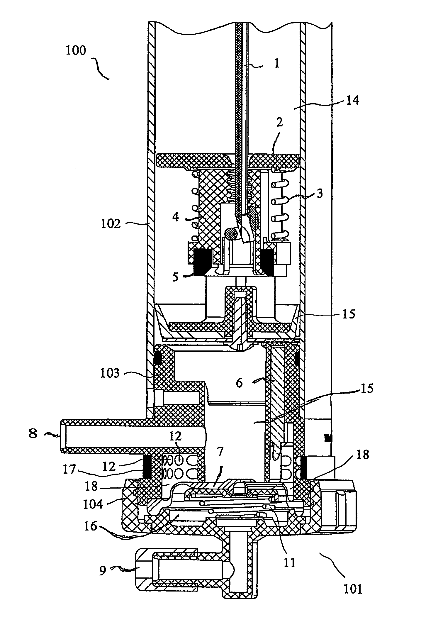
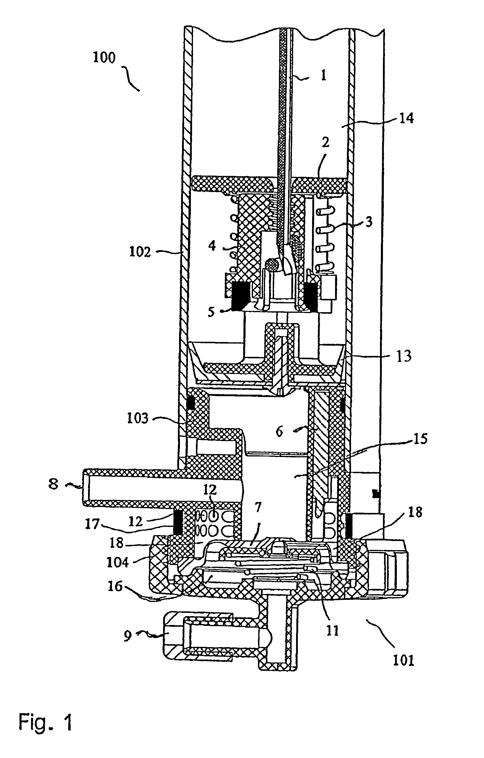
[0057]FIGS. 1 and 2 illustrate a milking unit cylinder 100 in cross-section which in the embodiment is configured to be a removal cylinder 100 or ACR cylinder (automatic cluster remover), comprising a cylinder sleeve 102, a piston 2 guided in said cylinder sleeve, a lid element 103 and a rapid ventilation valve 104.

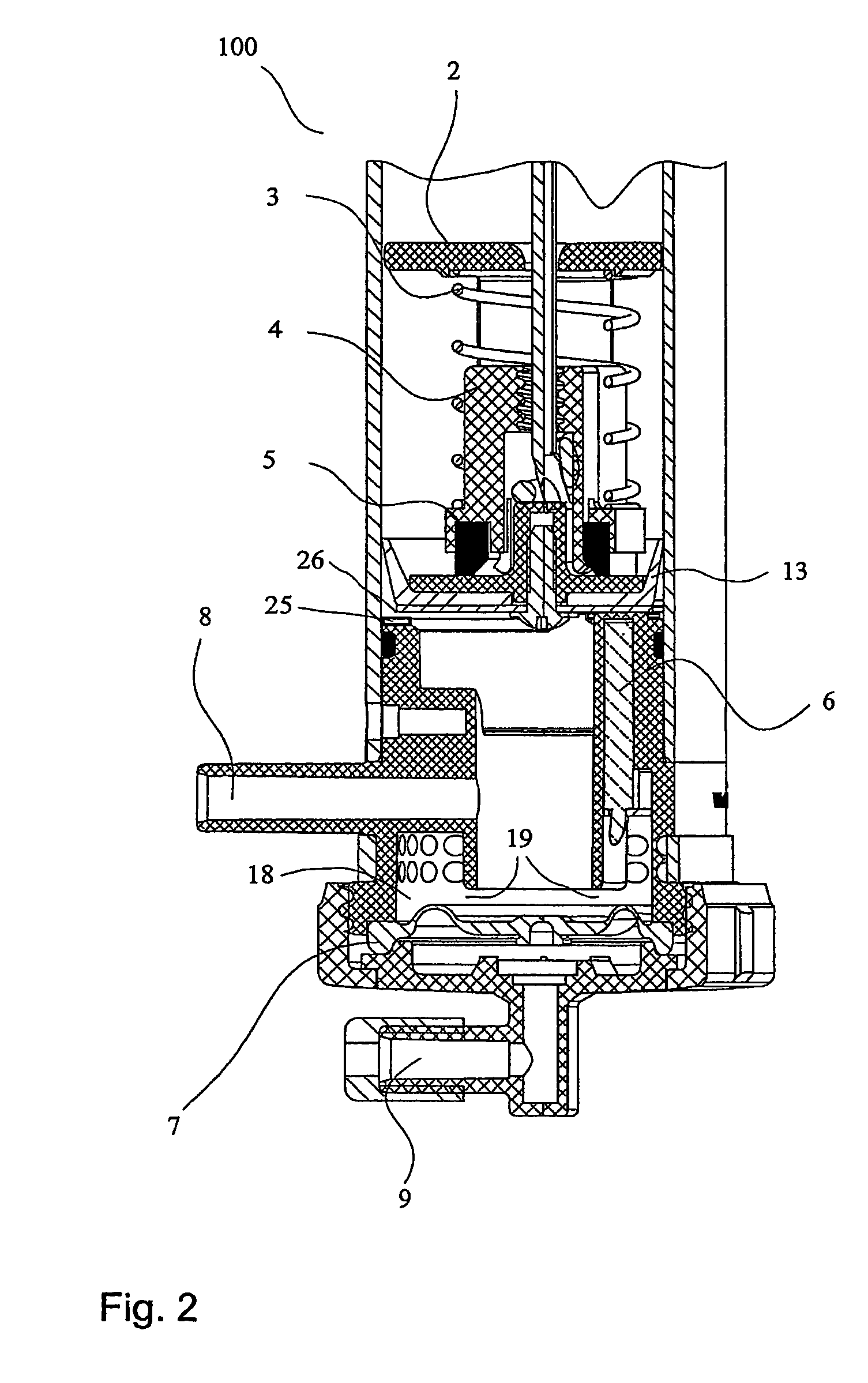
[0058]FIG. 1 illustrates the basic state where the milking unit cylinder 100 is in the stand-by state for milking, while FIG. 2 illustrates the state after sensor activation with the rapid ventilation open.

[0059]In the removal cylinder 100 the piston 2 has a flexible element 1 fastened to it. The flexible element 1 in the embodiment is a rope 1. The rope 1 is guided out of the cylinder 100 to the milking unit (not shown) that is freely movable, hanging from the rope 1. The rope may be routed over one or more deflection pulleys so as to make the milking unit cylinder 100 suitable for different vertical and horizontal mounting positions.

[0060]A cup seal 13 at the piston 2 r...


PUM


Abstract

A milking machine cylinder comprising a flexible element and at least one sensor element which detects at least a substantial weight relief of the flexible element in order to trigger a start signal for a milking process.

Description

FIELD AND BACKGROUND OF THE INVENTION[0001]The invention relates to a device and a method wherein gripping the milking unit triggers a start signal for a milking process.[0002]The prior art discloses in DE 25 54 998 C2 a device and a method wherein the starting process occurs automatically. The removal cylinder in this known system is in a substantially vertical position and pivotally fixed at its upper end. As the milking unit is gripped, said milking unit is displaced toward the animal such that the pivotable removal cylinder is displaced from its vertical position. Said displacing the removal cylinder will enable a switch that generates the start signal for the milking process. The rope is released. When the cylinder has been applied it will—due to gravitation—return to its vertical position in which it remains until the end of milking. After the removal signal the cylinder is biased, thus again assuming a slanted position. The milking unit is removed and the cylinder with the mi...

Claims


Application Information

Patent Timeline
IPC IPC(8): A01J5/00A01J5/007A01J5/017
CPCA01J5/017A01J5/007
Inventor STOLTE, FRIEDRICHKRONE, OTTOSUHR, OLAF
Owner GEA FARM TECH
Why Eureka
Try Eureka