Piston pump with cam follower arrangement

a follower arrangement and piston pump technology, applied in the field of pumps, can solve the problems of high cost of motor control arrangement, inefficient system energy utilization, noticeable pump output pulsation,

Active Publication Date: 2011-05-10
CARLISLE FLUID TECH UK LTD
View PDF39 Cites 55 Cited by
  • Summary
  • Abstract
  • Description
  • Claims
  • Application Information

AI Technical Summary

Problems solved by technology

Air motors require an external source of compressed air in order to operate, and it is recognised that such systems are relatively inefficient in terms of energy utilisation.
Moreover the change in drive direction at each end of reciprocatory stroke of an air motor is relatively slow giving rise to noticeable pulsation in the output of the pump.
U.S. Pat. No. 5,220,259 discloses a single reciprocating piston pump of relatively large stroke driven by a D.C. electric motor, an arrangement which is disadvantageous in requiring a complex, and therefore expensive control arrangement for the motor.

Method used


Image

  • Piston pump with cam follower arrangement
  • Piston pump with cam follower arrangement
  • Piston pump with cam follower arrangement

Examples


Embodiment Construction

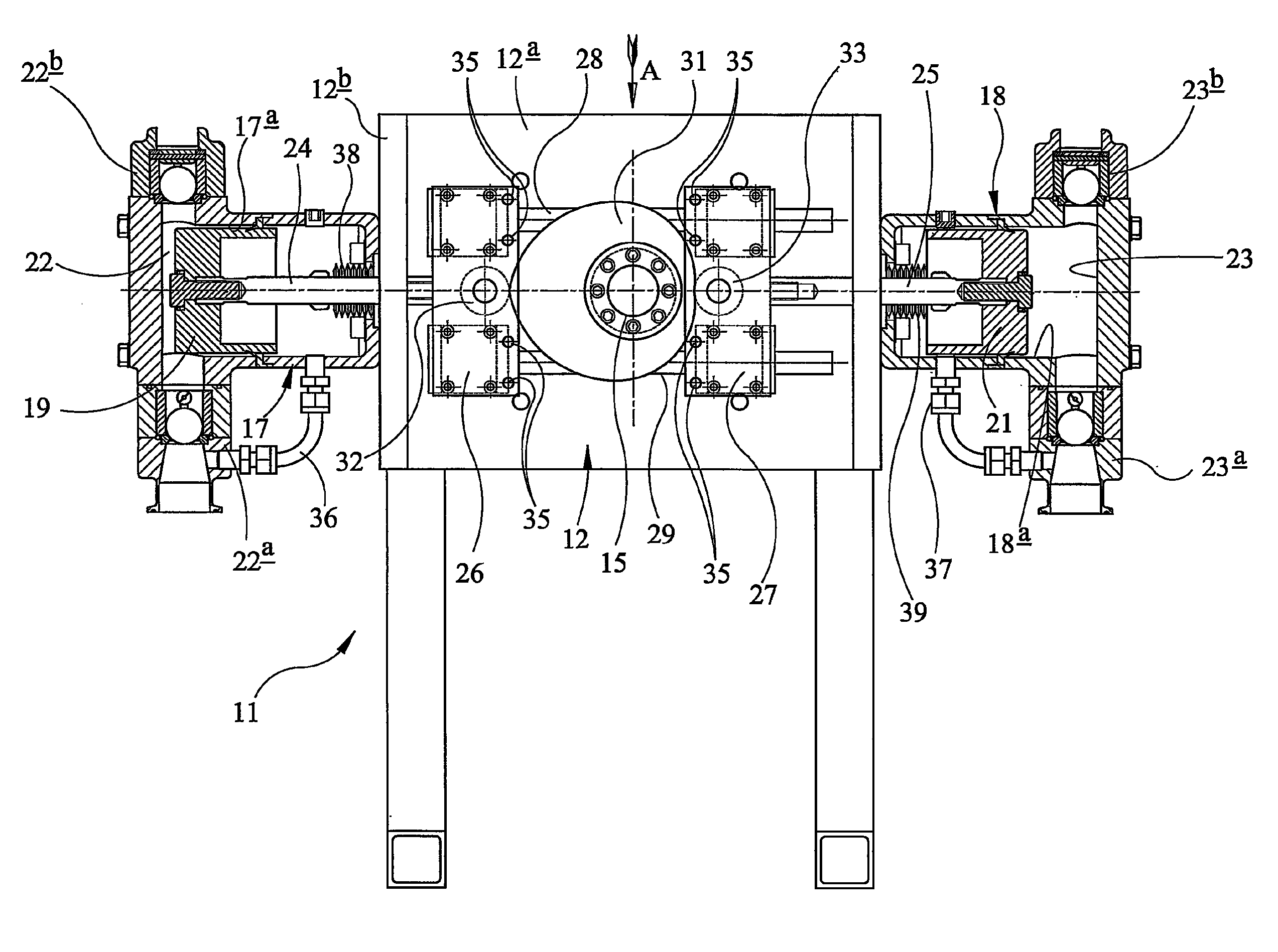
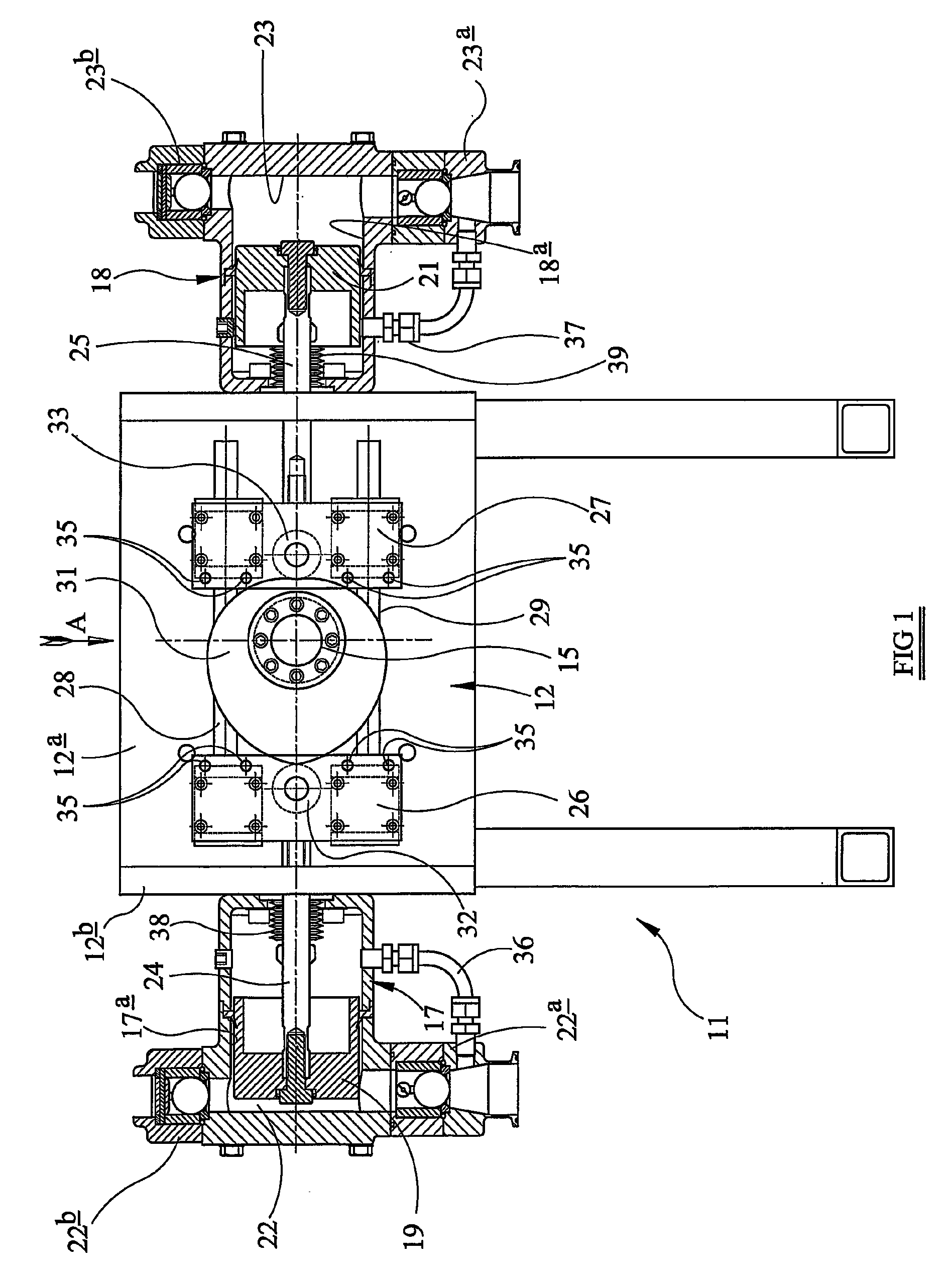
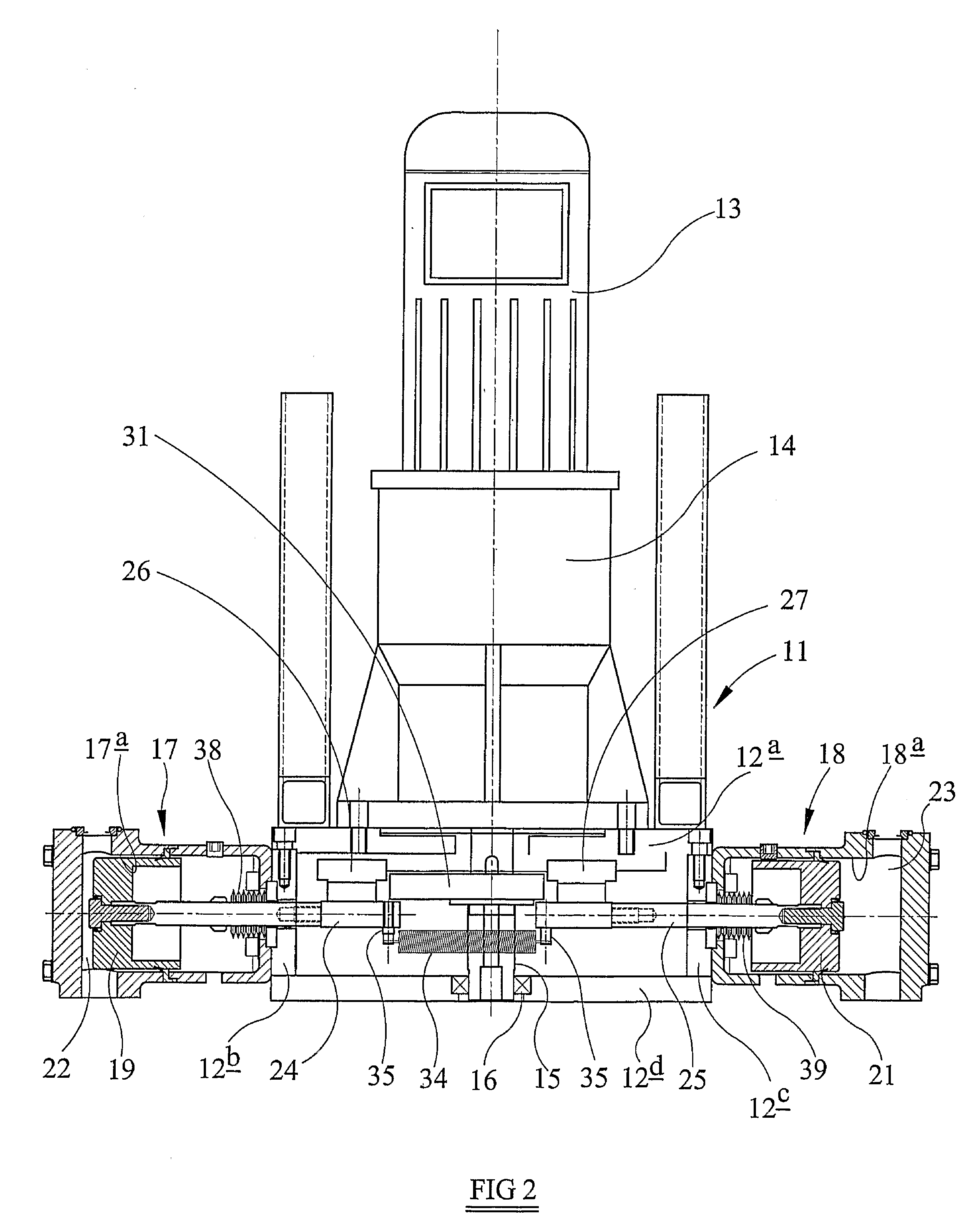
Referring to the drawings the pump which is primarily, but not exclusively, intended for supplying liquid paint to a pressure loop or paint circuit in turn supplying one or more spray guns, comprises a rigid supporting frame 11 including a mounting block 12 having a base plate 12a and upstanding, parallel, spaced side plates 12b, 12c extending at right angles to the base plate 12a. Although omitted from FIG. 1 for clarity, it can be seen from FIG. 2 that a front plate 12d extends parallel to the base plate 12a and is spaced therefrom by the side plates 12b, 12c. The plates 12a, 12b, 12c, 12d are secured together in any convenient manner, for example by means of bolts, to define a rigid box-like structure.

Bolted to the rear face of the plate 12a and extending at right angles thereto is a reduction gearbox 14 carrying, at its end remote from the plate 12a, an A.C. electric induction motor 13. The rotational axis of the rotor of the motor 13 is coincident with the longitudinal axis of ...


PUM


Abstract

A pump primarily for liquid paint includes first and second pistons reciprocable rectilinearly in respective first and second cylinders. The first and second pistons are moved relative to their respective pistons by operation of an A. C. electric motor the rotary output shaft of which is coupled to the first and second pistons by a constant velocity cam and a cam follower mechanism converting rotary motion of the output shaft into reciprocatory motion of the first and second pistons 180° out of phase with one another.

Description

RELATED APPLICATIONSThe present application is a National Phase application based on International Application Number PCT / GB2004 / 005219, filed Dec. 14, 2004, which claims priority from, British Application Number 0329585.4, filed Dec. 20, 2003, the disclosure of which is hereby incorporated by reference herein in its entirety.TECHNICAL FIELDThis invention relates to a pump, primarily but not exclusively for supplying liquid paint to a pressure loop serving one or more spray guns.BACKGROUND ARTU.S. Pat. No. 5,094,596 discloses a pump having a pair of opposed and interconnected pistons reciprocable in respective cylinders to pump paint. The interconnected pistons are driven in their reciprocatory motion by an air motor and while one piston and cylinder arrangement is pumping paint to supply paint under pressure into a pressure loop, the other piston and cylinder arrangement is being re-charged by drawing paint from a reservoir into the cylinder for subsequent discharge therefrom into ...

Claims


Application Information

Patent Timeline
Patent Type & Authority Patents(United States)
IPC IPC(8): F04B17/03F04B23/06F16H53/00F04B9/04
CPCF04B9/042F04B17/03Y10T74/2107Y10T74/2101F04B2201/0201F04B9/02F04B9/04
Inventor SMITH
Owner CARLISLE FLUID TECH UK LTD
Why Eureka
Try Eureka