Optical connector and an optical tomographic imaging system using the same

a technology of optical connectors and optical tomography, applied in the field of optical connectors and optical tomographic imaging systems using the same, can solve the problems of reducing signal-to-noise ratio, reducing signal-to-noise ratio, attenuating the light return of objects under measurement, etc., and achieves the effect of preventing damage or breakage of the tips of the two connected optical fibers and efficient acquisition

Active Publication Date: 2011-05-10
TERUMO KK
View PDF36 Cites 10 Cited by
  • Summary
  • Abstract
  • Description
  • Claims
  • Application Information

AI Technical Summary

Benefits of technology

[0007]An optical connector ensures light guiding with an increased transmission efficiency when the end faces of the optical fibers are placed into a close contact leaving no space therebetween. In particular, an optical connector of APC type that connects optical fibers each having an end face inclined by a given angle is capable of reducing attenuation of light (or return loss) that is caused by reflection of light on the contact surfaces of the optical fibers.

Problems solved by technology

While the transmission efficiency may be increased with an optical connector whereby the end faces of optical fibers are placed in contact or in close contact with each other, problems are posed that returning light from the object under measurement attenuates as light is reflected or refracted at the opposite end faces of two optical fibers or the signal-to-noise ratio decreases as light reflected by the end faces of the optical fibers is guided to a detector along with the returning light.
However, since, with an optical tomographic imaging system, the amount of returning light is small in relation to the amount of measuring light as described above, the signal-to-noise ratio decreases because of return loss and other causes even when an optical connector of APC type is used.
There is another problem that when attaching or detaching an optical fiber to replace an optical fiber or a light source or to perform other task, the tip of the optical fiber can be damaged or broken as the optical fibers contact each other.

Method used


Image

  • Optical connector and an optical tomographic imaging system using the same
  • Optical connector and an optical tomographic imaging system using the same
  • Optical connector and an optical tomographic imaging system using the same

Examples


Embodiment Construction

[0032]Now, the inventive optical connector and the optical tomographic imaging system using the same will be described in detail referring to the embodiments illustrated in the attached drawings.

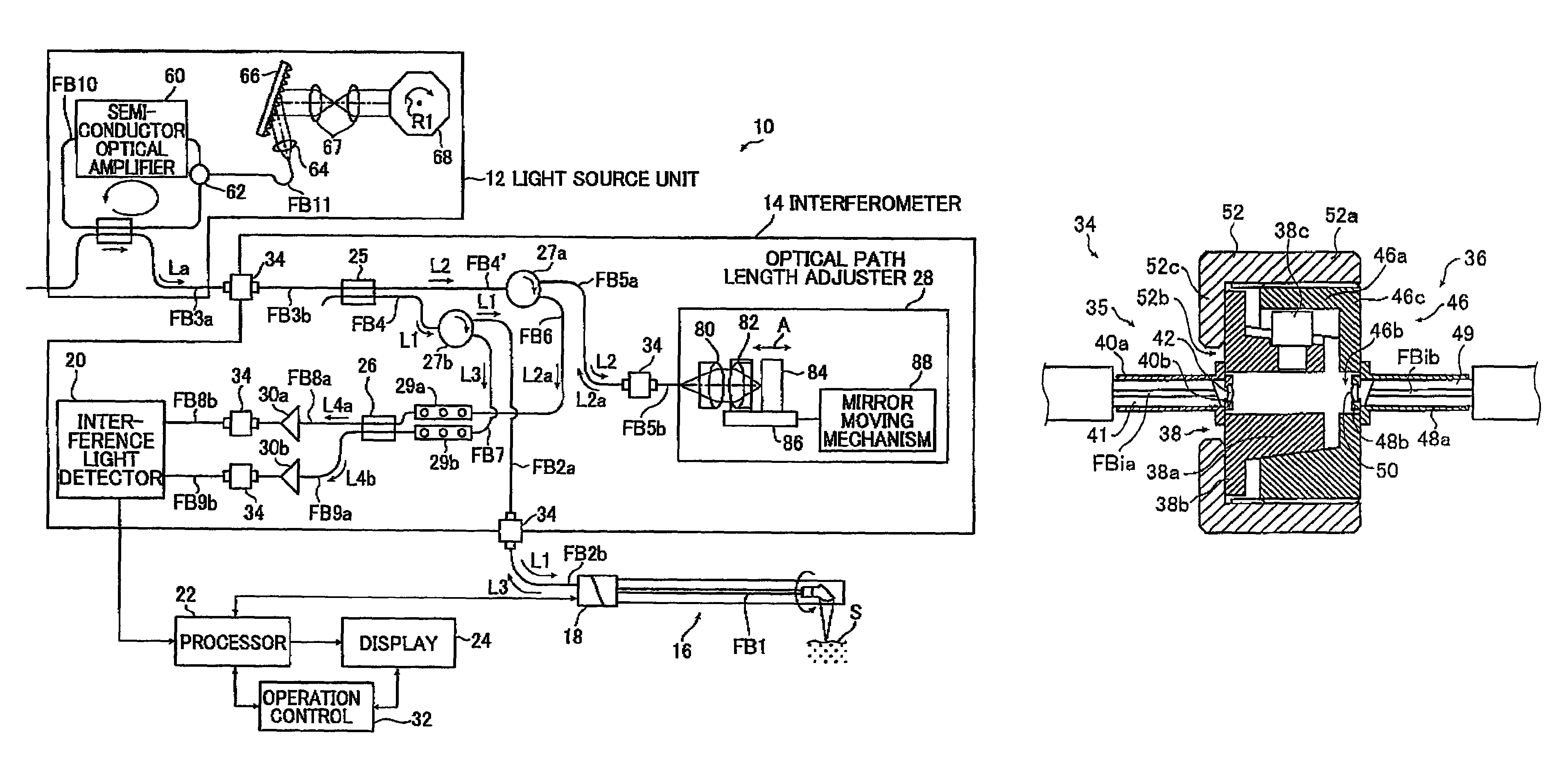
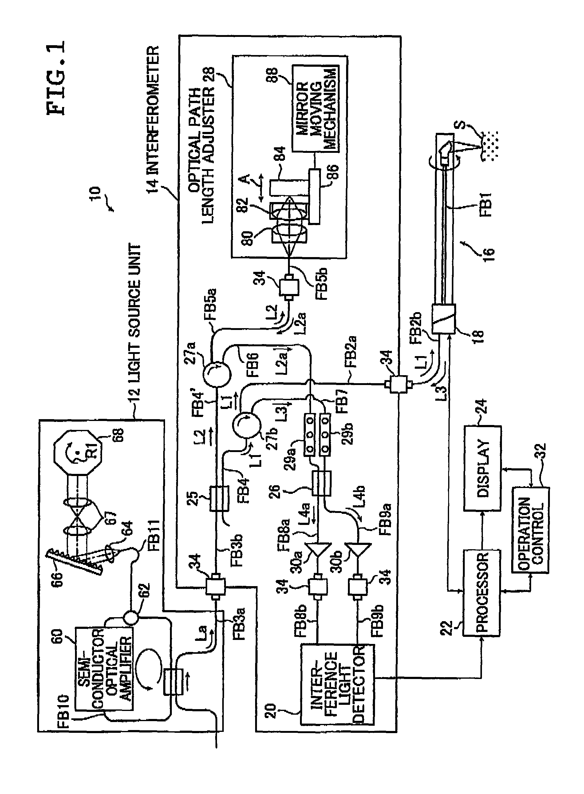
[0033]FIG. 1 is a block diagram illustrating a schematic configuration of an embodiment of the inventive optical tomographic imaging system using the inventive optical connector.

[0034]An optical tomographic imaging system 10 according to the invention illustrated in FIG. 1 acquires a tomographic image of an object under measurement by a measuring method based upon optical coherence tomography or OCT. The optical tomographic imaging system 10 comprises: a light source unit 12 for emitting light La; an interferometer 14 including a splitter 25 for splitting the light La emitted by the light source unit 12 into measuring light L1 and reference light L2, a combiner 26 for combining returning light L3 from an object under measurement or a sample under test and reference light L2a to produce inter...


PUM


Abstract

The optical connector includes a holder unit, a first optical fiber fixedly supported by the holder unit and having an inclined end face, a first collimating lens spaced from the inclined end face, a mounting unit supported relative to the holder unit, a second optical fiber disposed opposite the first collimating lens and having an inclined end face, a second collimating lens disposed between the first collimating lens and the second optical fiber and spaced from the inclined end face of the second optical fiber, wherein an optical transmission system comprising the first optical fiber and the first collimating lens is symmetric to an optical transmission system comprising the second optical fiber and the second collimating lens with respect to a plane perpendicular to the optical axis.

Description

[0001]The entire contents of the literature cited in this specification are incorporated herein by reference.BACKGROUND OF THE INVENTION[0002]The invention relates to an optical connector for guiding light from one optical fiber to another optical fiber and an optical tomographic imaging system using the optical connector and more particularly to an optical connector achieving a noncontact connection between light guiding optical fibers to guide light from one optical fiber to another optical fiber and an optical tomographic imaging system for irradiating an object to be measured with light to acquire an optical tomographic image from returning light reflected by the object under measurement.[0003]Acquisition of a cross-sectional image of a sample under measurement such as biological tissue without cutting thereinto may be achieved using an optical tomographic imaging system employing optical coherence tomography (OCT) measuring.[0004]The OCT measuring is a kind of optical interfero...

Claims


Application Information

Patent Timeline
Patent Type & Authority Patents(United States)
IPC IPC(8): G01B9/02
CPCG02B6/327G02B6/3831G01N21/4795G02B6/3818G02B6/3853G02B6/3851G02B6/3826
Inventor MASUDA, TADASHI
Owner TERUMO KK
Why Eureka
Try Eureka