Supercharge Your Innovation With Domain-Expert AI Agents!

Row decoder for non-volatile memory devices, in particular of the phase-change type

a non-volatile memory device and decoder technology, applied in the direction of information storage, static storage, digital storage, etc., can solve the problem that power consumption levels still constitute an important design limitation

Active Publication Date: 2011-05-10
STMICROELECTRONICS SRL
View PDF6 Cites 6 Cited by
  • Summary
  • Abstract
  • Description
  • Claims
  • Application Information

AI Technical Summary

Benefits of technology

The patent text describes a new design for a row decoder, which is a component of a phase-change memory device. The new design solves problems associated with existing decoders and optimizes its electrical characteristics for use with PCMs. The new design includes a global decoder and a local decoder. The global decoder addresses the first and second global wordlines, while the local decoder addresses a selected array wordline based on the values of the global wordlines and second address signals. The local decoder has two circuit branches that provide current paths for reading and programming operations, respectively. The patent also includes a phase-change memory device with the new row decoder and a system with the memory device. The technical effects of the patent text include improved performance and reliability of the phase-change memory device.

Problems solved by technology

However, given that the row decoder requires a high area occupation, it is necessary to reach a compromise between the static power required in the row selection and the efficiency in the area occupation of the non-volatile memory device.
Even though this decoding architecture enables, as compared to traditional solutions, an improved compromise to be reached between the dynamic power used for biasing the selected wordlines and the area occupation of the row decoder, the power consumption levels still constitute an important design limitation, especially in the case of phase-change non-volatile memory devices.

Method used


Image

  • Row decoder for non-volatile memory devices, in particular of the phase-change type
  • Row decoder for non-volatile memory devices, in particular of the phase-change type
  • Row decoder for non-volatile memory devices, in particular of the phase-change type

Examples


Embodiment Construction

[0025]As will be described in detail in what follows, an aspect of the present disclosure envisages defining, in a hierarchical row-decoder architecture, two different current paths for selection of the wordlines of the memory array: a first path dedicated to the reading operations, and defined for this reason in what follows as “reading path”; and a second path dedicated to the programming operations, and defined for this reason in what follows as “programming path”.

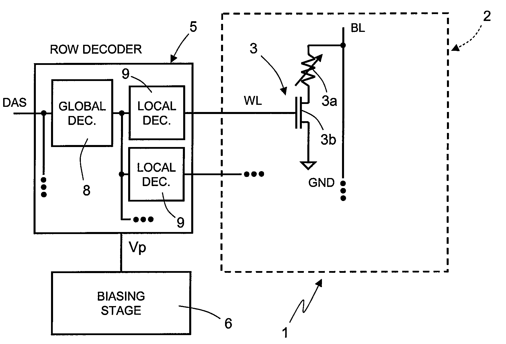
[0026]In FIG. 1, a non-volatile memory device, in particular of a PCM type, designated as a whole by the reference number 1, is shown schematically, limitedly to just the parts that provide an understanding of the present disclosure.

[0027]In particular, the non-volatile memory device 1 comprises a memory array 2, constituted by a plurality of memory cells 3, arranged according to array wordlines WL and array bitlines BL. The memory cells 3 are identical to one another and comprise a phase-change element 3a and a selecto...


PUM


Abstract

A hierarchical row decoder is for a phase-change memory device provided with an array of memory cells organized according to a plurality of array wordlines and array bitlines. The row decoder has a global decoder that addresses first and a second global wordlines according to first address signals; and a local decoder, which is operatively coupled to the global decoder and addresses a respective array wordline according to the value the first and second global wordline and second address signals. The local decoder has a first circuit branch providing, when the first global wordline is addressed, a first current path between the array wordline and a first biasing source during a reading operation; and a second circuit branch providing, when the second global wordline is addressed, a second current path, distinct from the first current path, between the array wordline and a second biasing source during a programming operation.

Description

BACKGROUND[0001]1. Technical Field[0002]The present disclosure relates to a row decoder for non-volatile memory devices, in particular of the phase-change type, to which the following treatment will make particular reference, without this implying any loss of generality.[0003]2. Description of the Related Art[0004]Non-volatile phase-change memories (PCMs) are known, in which, for storing information, the characteristics of materials that have the property of switching between phases having different electrical characteristics are exploited. For example, these materials can switch between a disorderly amorphous phase and an orderly crystalline or polycrystalline phase, and the two phases are associated to resistivity of considerably different values, and consequently to a different value of a stored datum. For example, the elements of the Group VI of the periodic table, such as tellurium (Te), selenium (Se), or antimonium (Sb), referred to as chalcogenides or chalcogenic materials, c...

Claims


Application Information

Patent Timeline
Patent Type & Authority Patents(United States)
IPC IPC(8): G11C11/00G11C8/00
CPCG11C8/08G11C8/10G11C13/0028G11C13/0023G11C13/0004
Inventor DE SANDRE, GUIDO
Owner STMICROELECTRONICS SRL
Features
  • R&D
  • Intellectual Property
  • Life Sciences
  • Materials
  • Tech Scout
  • Unparalleled Data Quality
  • Higher Quality Content
  • 60% Fewer Hallucinations
Learn More