Method for computing an exact impulse response of a plane acoustic reflector at zero offset due to a point acoustic source

a plane acoustic reflector and exact impulse response technology, applied in the field of exact impulse response of plane acoustic reflector at zero offset due to a point acoustic source, can solve the problems of inability to determine the time-spatial position of seismic trace, inability to solve the solution, and inability to use line sources infinitely

Inactive Publication Date: 2011-05-10
COUNCIL OF SCI & IND RES
View PDF1 Cites 31 Cited by
  • Summary
  • Abstract
  • Description
  • Claims
  • Application Information

AI Technical Summary

Benefits of technology

[0017]Yet another object of the present invention is to provide a method for computing exact zero-offset reflection response of a circular reflector observed at its central axis and up to a limited span of time.
[0018]Still yet another object of the present invention is to provide a method for computing accurate synthetic zero-offset reflection response of a planar reflector using which seismic migration and inversion algorithms can be tested and validated.

Problems solved by technology

The information appearing on a single seismic trace does not allow one to determine the time-spatial position of the reflecting point.
One drawback of the formula is that a line source is of infinite spatial extent and does not represent real seismic sources.
Another drawback is that the formula is not explicit in that the solution requires, for each elapsed time, since the onset of the source, calculation of the corresponding horizontal wave slowness, which in turn yields the value of the conforming vertical slowness required in the algebraic formula.
Another drawback is that the solution, unlike the algebraic formula of the present invention, does not have a specific term representing the asymptotic solution.
One drawback of the said derivation is that their solution, unlike the algebraic formula underlying the present invention, does not have a specific term representing the asymptotic solution.
A particular drawback is that the solution is valid only for a rigid boundary corresponding to a reflection coefficient of unity.
The foremost drawback is that the solution is incorrect in view of the following.
Further, according to Aki and Richards (1980) the reflected wavefield for a plane reflector has a longer tail in time domain than the incident wave, a result inconsistent with the solution of Hilterman (1975), according to which the complete wave equation response has the same time span as the incident wave.
Therefore, the solution of Hilterman (1975) for the zero-offset reflection response of a plane acoustic reflector is incorrect.

Method used


Image

  • Method for computing an exact impulse response of a plane acoustic reflector at zero offset due to a point acoustic source
  • Method for computing an exact impulse response of a plane acoustic reflector at zero offset due to a point acoustic source
  • Method for computing an exact impulse response of a plane acoustic reflector at zero offset due to a point acoustic source

Examples


example 1

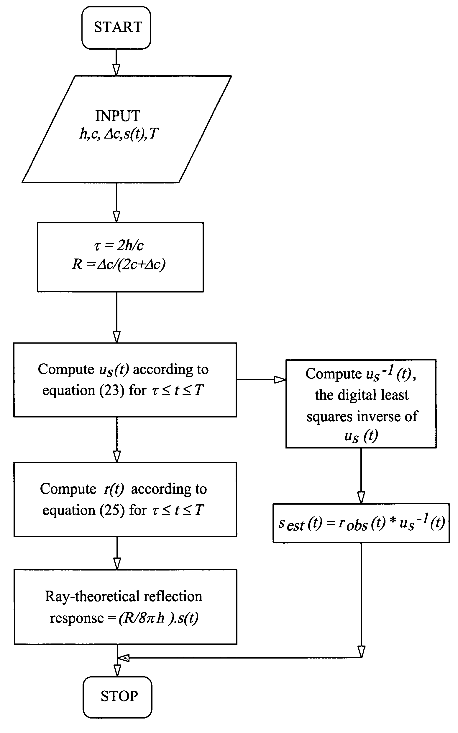
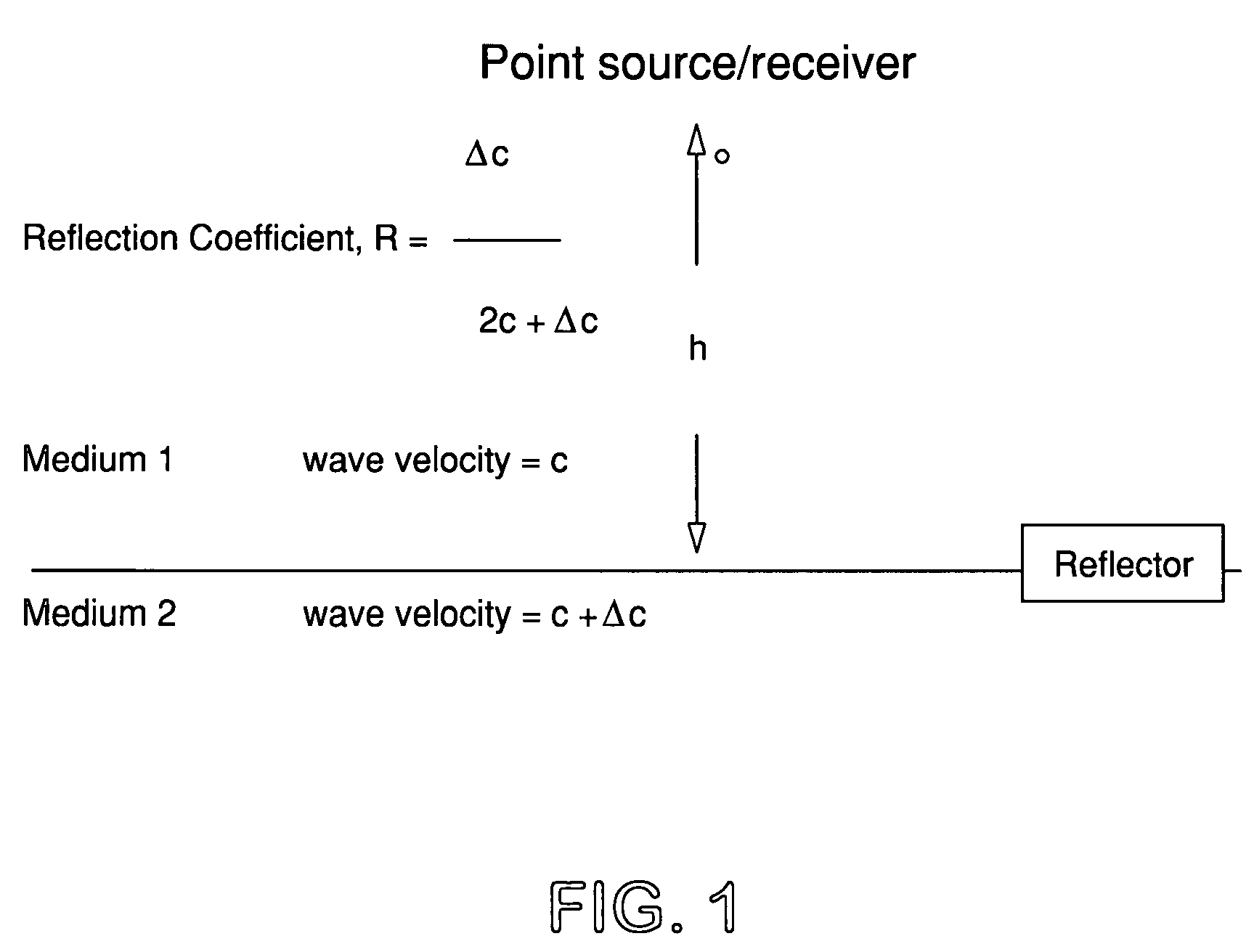
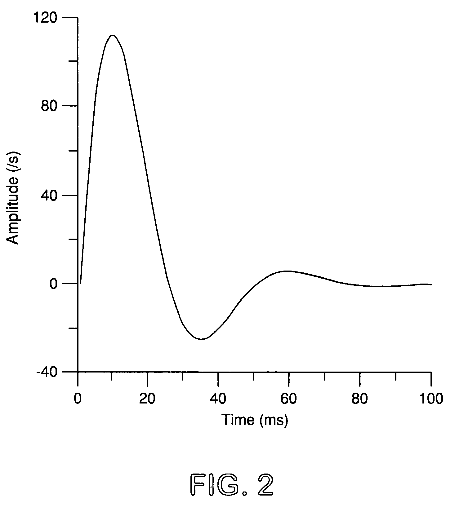
[0133]This example consists of computing the zero-offset reflection response of a plane reflector due to a point source and a given seismic source-time function. The reflector and its parameters are depicted in FIG. 1 and FIG. 3. The source-time function is represented in FIG. 2. Explicitly, the source-time function, s(t) has representation according to equation

s(t)=212exp(−60t).sin(40πt),  Eq. 28

which is a special case of Berlage signal (Cerveny, 2001). Equation (25) is used to compute the reflection response. The functions s(t) and H(t−τ) / t3 are first digitally represented with a sampling interval of 1 millisecond and then their convolution is computed. The computation of r(t), the zero-offset reflection response is then straightforward following equation (25). This response is depicted in FIG. 3.

[0134]The response computed can serve several goals. It would provide a computed standard against which the reflection response computed by a seismic numerical modeling algorithm for the ...

example 2

[0137]This example demonstrates the role of equation (25) in identifying a situation when a ray-theoretical solution is accurate enough and when it is not. FIG. 3 represents the complete wave-theoretical solution for a source-reflector (FIG. 1) specified in the caption of FIG. 3 and the source-time function depicted in FIG. 2. FIG. 4 represents the ray-theoretical solution for the same circumstance. FIG. 5 depicts the difference between the wave-theoretical and the ray-theoretical solution. It is evident that the magnitude of the maximum difference is a substantial fraction (˜13%) of the maximum of the wave-theoretical solution. Thus, the ray-theoretical solution lacks efficacy in this instance.

[0138]FIG. 6 depicts the complete wave-theoretical solution for a point acoustic source-reflector (FIG. 1) specified in the caption of FIG. 6 and the source-time function depicted in FIG. 2. The only difference with the source-reflector parameters specified in FIG. 3 is that h, the depth to t...


PUM


Abstract

Originating from a novel and an exact algebraic formula for the impulse response of a plane acoustic reflector at zero offset due to a point acoustic source the present invention provides a method for computing an exact impulse response of a plane acoustic reflector at zero offset due to a point acoustic source; and originating from the method, methods for testing and validating algorithms for numerical modeling of seismic reflection, seismic migration and seismic inversion; a method for testing the efficacy of ray-theoretical solution for a given source-reflector configuration; another method for computing zero-offset reflection response of a circular reflector at its central axis; yet another method for validating an interpretation of a reflector as a planar structure; still yet another method for estimating the seismic source-time function when the zero-offset reflection response of a plane reflector is given. Although the algebraic formula and the methods originating from it are, in a strict sense, valid for an acoustic earth and an acoustic source, these would also be of immense utility in the seismic industry where the earth is successfully approximated as an acoustic medium and a seismic source as an acoustic source.

Description

CROSS REFERENCE TO RELATED APPLICATION[0001]This application is a utility application and claims the benefit under 35 USC §119(a) of India Application No. 2626 / DEL / 2006 filed Dec. 7, 2006. This disclosure of the prior application is considered part of and is incorporated by reference in the disclosure of this application.BACKGROUND OF THE INVENTION[0002]1. Field of Invention[0003]The present invention relates to a method for computing an exact impulse response of a plane acoustic reflector at zero offset due to a point acoustic source useful for seismological applications.[0004]A novel and an exact algebraic formula for the impulse response of a plane acoustic reflector at zero offset due to a point acoustic source underlies the method cited in the present invention. An observation at zero offset represents the case when the seismic source and the receiver are located either at the same point or arbitrarily close to each other.[0005]2. Background and Prior Art of the Invention[0006]...

Claims


Application Information

Patent Timeline
Patent Type & Authority Patents(United States)
IPC IPC(8): G01V1/00
CPCG01V1/30
Inventor GHOSH, SANTI KUMAR
Owner COUNCIL OF SCI & IND RES
Why Eureka
Try Eureka