Method and system for reducing power plant emissions

a technology of power plant and greenhouse gas, which is applied in the direction of machines/engines, mechanical equipment, membrane technology, etc., can solve the problems of power plant power loss of approximately ten percent, current technology for separating carbon dioxide from other exhaust gases within the exhaust stream is relatively expensive, etc., to reduce the operating temperature of the exhaust stream, and facilitate the effect of reducing emissions

Inactive Publication Date: 2011-05-17
GENERAL ELECTRIC CO
View PDF17 Cites 79 Cited by
  • Summary
  • Abstract
  • Description
  • Claims
  • Application Information

AI Technical Summary

Benefits of technology

[0004]In one aspect, a method for operating a power plant to facilitate reducing emissions, wherein the power plant includes a gas turbine engine assembly and a carbon dioxide (CO2) separator. The method includes increasing an operating pressure of exhaust stream discharged from the gas turbine engine assembly, reducing the operating temperature of the exhaust stream, separating substantially all the CO2 entrained within the exhaust stream utilizing the CO2 separator to produce a CO2 lean exhaust stream, reducing the operating temperature of the CO2 lean exhaust stream, and utilizing the cooled CO2 lean exhaust stream to facilitate reducing an operating temperature of air entering the gas turbine engine assembly.
[0005]In another aspect, a power plant is provided. The power plant includes a gas turbine engine assembly, a carbon dioxide (CO2) separator in flow communication with said gas turbine engine assembly configured to substantially remove the CO2 entrained within the gas turbine engine exhaust stream utilizing the CO2 separator to produce a CO2 lean exhaust stream, and an expander configured to reduce the operating temperature of the CO2 lean exhaust stream such that the cooled lean exhaust stream may be utilized to facilitate reducing an operating temperature of air entering the gas turbine engine assembly.

Problems solved by technology

As a result, current technology for separating carbon dioxide from other exhaust gases within the exhaust stream is relatively expensive and may result in a power plant power loss of approximately ten percent.

Method used


Image

  • Method and system for reducing power plant emissions
  • Method and system for reducing power plant emissions
  • Method and system for reducing power plant emissions

Examples


Embodiment Construction

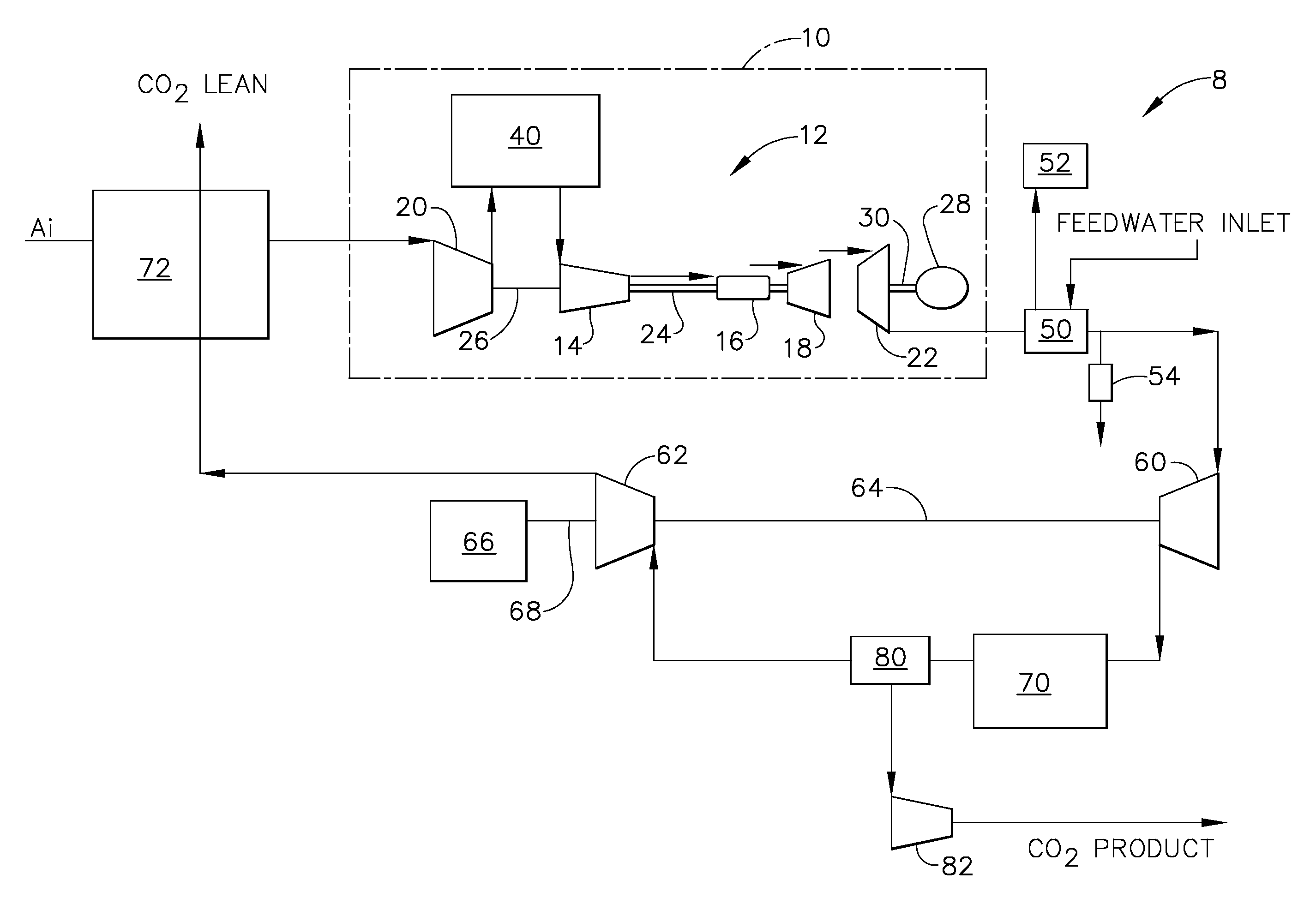
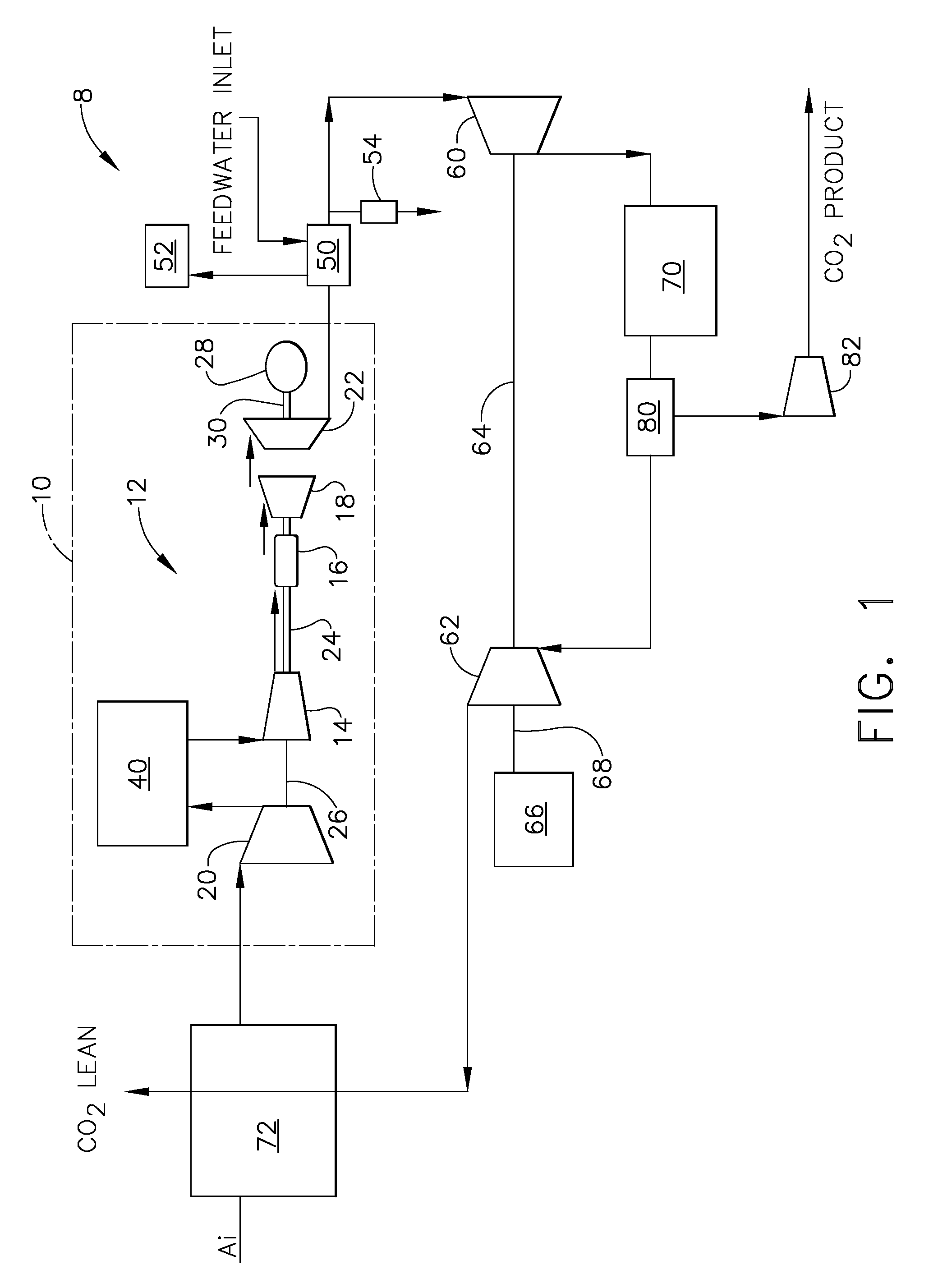
[0010]FIG. 1 is a schematic illustration of a power plant 8 that includes an exemplary gas turbine engine assembly 10. Gas turbine engine assembly 10 includes a core gas turbine engine 12 that includes a high-pressure compressor 14, a combustor 16, and a high-pressure turbine 18. Gas turbine engine assembly 10 also includes a low-pressure compressor 20 and a low-pressure turbine 22. High-pressure compressor 14 and high-pressure turbine 18 are coupled by a first shaft 24, and low-pressure compressor 20 is coupled to an intermediate pressure turbine (not shown) by a second shaft 26. In the exemplary embodiment, low-pressure turbine 22 is coupled to a load, such as a generator 28 via a shaft 30. In the exemplary embodiment, core gas turbine engine 12 is an LMS100 available from General Electric Aircraft Engines, Cincinnati, Ohio.

[0011]In the exemplary embodiment, gas turbine engine assembly 10 may include an intercooler 40 to facilitate reducing the temperature of the compressed airflo...


PUM


Abstract

A method for operating a power plant to facilitate reducing emissions, wherein the power plant includes a gas turbine engine assembly and a carbon dioxide (CO2) separator. The method includes increasing an operating pressure of exhaust gas discharged from the gas turbine engine assembly, separating substantially all the CO2 entrained within the gas turbine engine utilizing the CO2 separator to produce a CO2 lean airstream, reducing the operating temperature of the CO2 lean airstream, and utilizing the cooled CO2 lean airstream to facilitate reducing an operating temperature of air entering the gas turbine engine assembly.

Description

BACKGROUND OF THE INVENTION[0001]This application relates generally to power generating facilities and, more particularly, to a power generating system and method for reducing the emission of greenhouse gases.[0002]Air pollution concerns worldwide have led to stricter emissions standards. These standards regulate the emission of oxides of nitrogen (NOx), unburned hydrocarbons (HC), carbon monoxide (CO), and carbon dioxide (CO2), generated by the power industry. In particular, carbon dioxide has been identified as a greenhouse gas, resulting in various techniques being implemented to reduce the concentration of carbon dioxide being discharged to the atmosphere.[0003]One such technique utilizes an amine process to separate the carbon dioxide from the other exhaust gases. More specifically, amine is injected into the exhaust stream of a known gas turbine engine prior to the exhaust stream being discharged to atmosphere. For example, when the exhaust stream is discharged to atmosphere, ...

Claims


Application Information

Patent Timeline
Patent Type & Authority Patents(United States)
IPC IPC(8): F02C1/00F02G1/00
CPCF02C3/34F02C7/143B01D2257/504Y02T50/675Y02C10/06Y02E20/16Y02C10/04Y02C20/40Y02T50/60
Inventor JOSHI, NARENDRA DIGAMBERMONTGOMERY, LAUTARO ASPIAZUSTEGMAIER, JAMES WILLIAM
Owner GENERAL ELECTRIC CO
Why Eureka
Try Eureka