

Installation for packaging a liquid product in receptacles
a technology for packaging and liquid products, applied in the direction of liquid bottling, packaging under special atmospheric conditions, containers, etc., can solve the problems of very small quantity of product that is discarded and filling is therefore very quick, and achieve the effect of minimizing the quantity of product lost and changing quickly
- Summary
- Abstract
- Description
- Claims
- Application Information
AI Technical Summary
Benefits of technology
Problems solved by technology
Method used
Image

Examples
Embodiment Construction
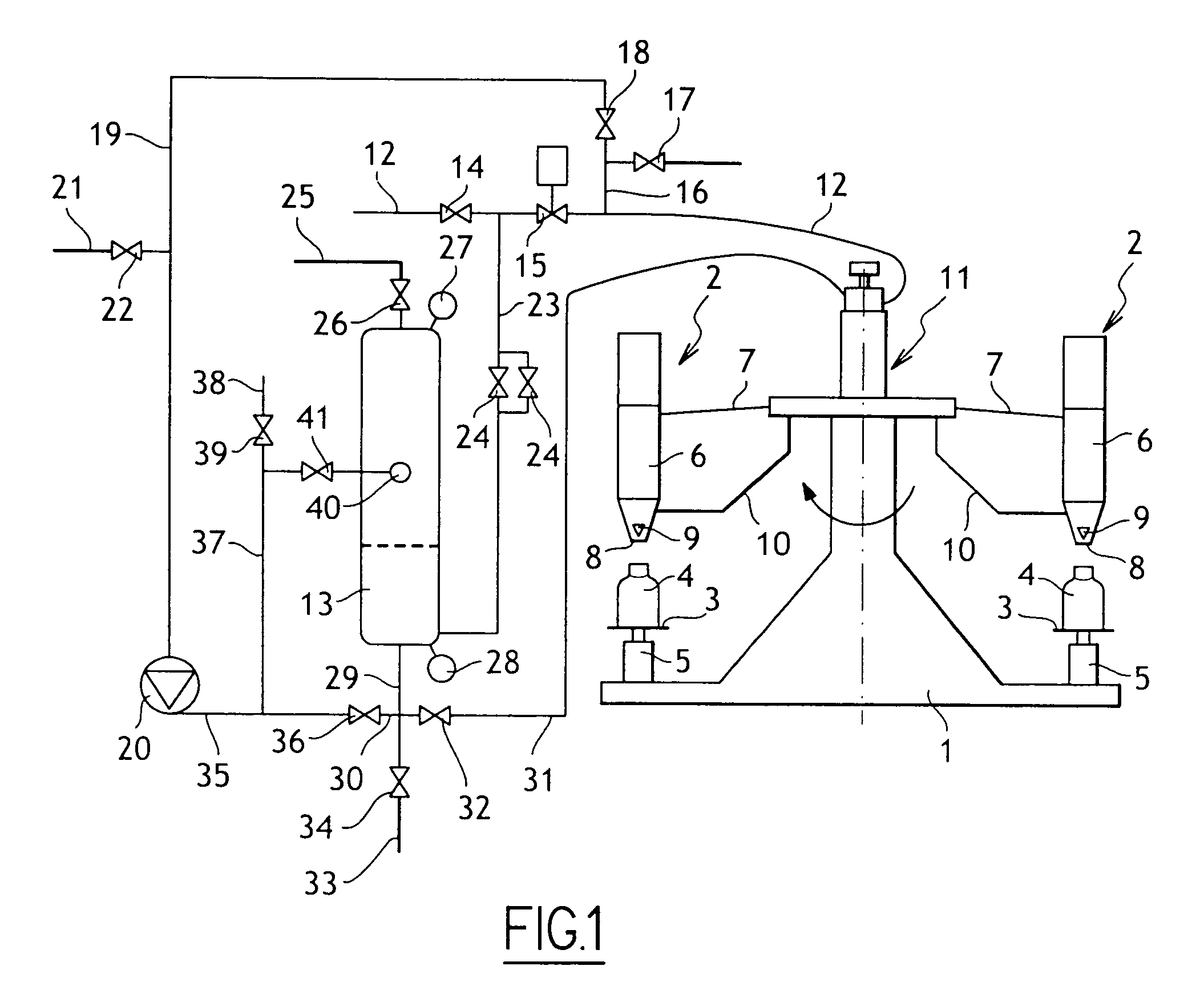
[0016]With reference to FIG. 1, the filler installation shown comprises in conventional manner a rotary carousel comprising a rotary structure 1 having filler stations mounted thereon, each comprising a filler spout 2 and a support member 3 for supporting a receptacle 4 under the filler spout, each support member 4 being associated with a weighing member 5 serving to control the corresponding filler spout in association with a control unit, not shown.
[0017]Each filler spout 2 comprises a spout body 6 having a top end connected to a filler spout feed duct 7 and a bottom end provided with an orifice 8 fitted with a controlled valve 9.
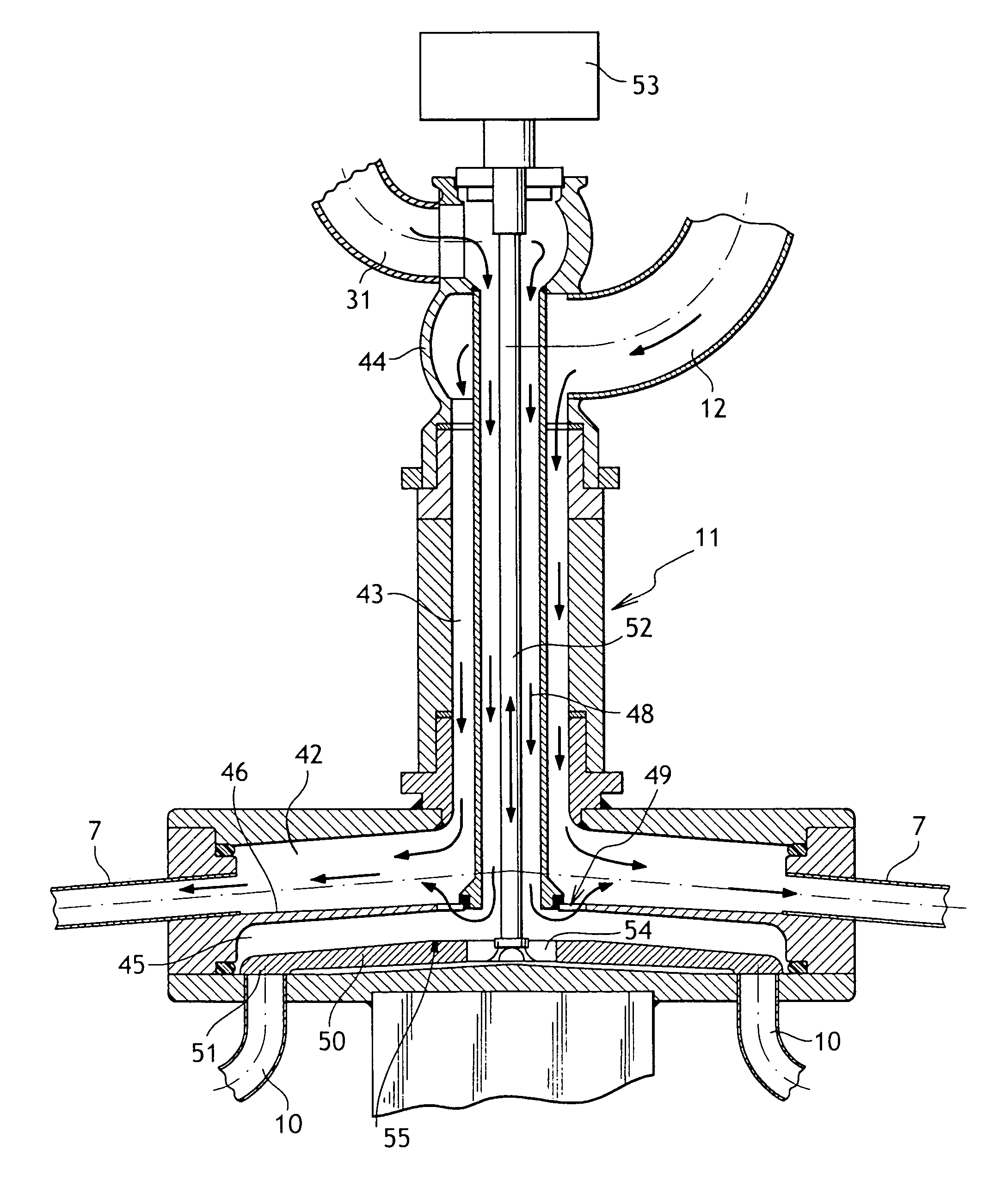
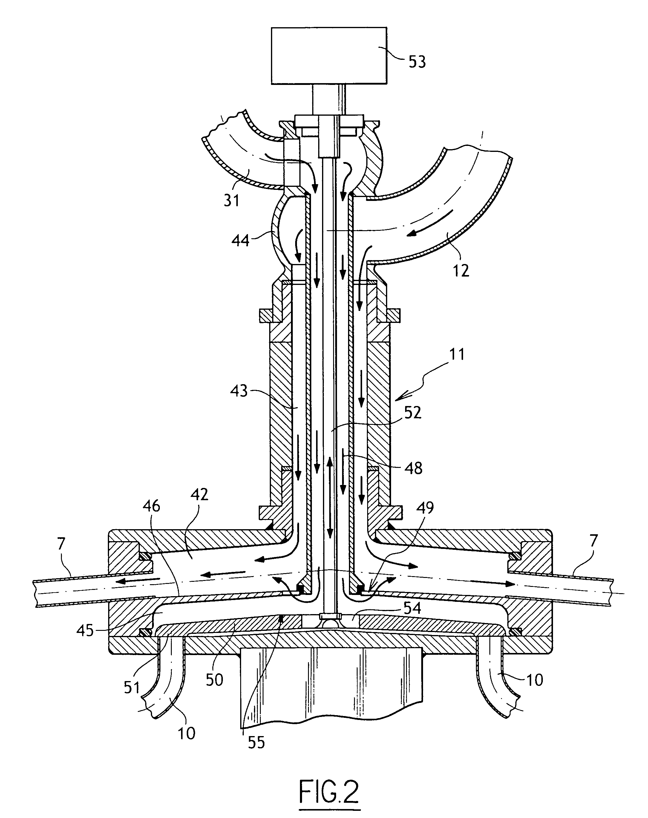
[0018]According to the invention, each filler spout 2 is also fitted with a looping duct 10 having one end secured to the spout body 6 and opening out into the spout body above the valve 9, and an opposite end connected to a multiport link member 11 of structure that is described below with reference to FIG. 2. The multiport link member 11 is connected bo...
PUM
| Property | Measurement | Unit |
|---|---|---|
| symmetry | aaaaa | aaaaa |
| structure | aaaaa | aaaaa |
| length of time | aaaaa | aaaaa |
Abstract
Description
Claims
Application Information