Supercharge Your Innovation With Domain-Expert AI Agents!

Rotary cutting mat

a cutting mat and rotary technology, applied in the field of cutting mats, can solve the problems of high cost, inability to keep the upper surface of the cutting mat flat, and inability to use the cutting surface in such a region, and achieve the effect of convenient selection and effective utilization of the reverse sid

Active Publication Date: 2011-05-17
OLFA
View PDF5 Cites 9 Cited by
  • Summary
  • Abstract
  • Description
  • Claims
  • Application Information

AI Technical Summary

Benefits of technology

The solution enables cost-effective production with a simple structure and a flat surface, preventing cutting line deflection and enhancing operational efficiency by allowing both sides of the mat to be used for cutting or alternative purposes.

Problems solved by technology

However, the rotary cutting mat in Japanese Utility Model Registration No. 3022789 confronts the following problems, since a rivet member is used to connect the base plate and the rotary mat.
This is because: if a rivet head is exposed on the upper surface of the rotary mat, the upper surface in such the region can not serve as a cutting mat.
Therefore, the structure of the mat becomes complicated, which increases the number of the components of the mat and the number of the manufacturing steps, resulting in higher cost.
Thus, the upper surface of the mat can not be kept in flat, and thus, cutting lines can be easily deflected on such the raised region of the mat.

Method used


Image

  • Rotary cutting mat
  • Rotary cutting mat
  • Rotary cutting mat

Examples


Embodiment Construction

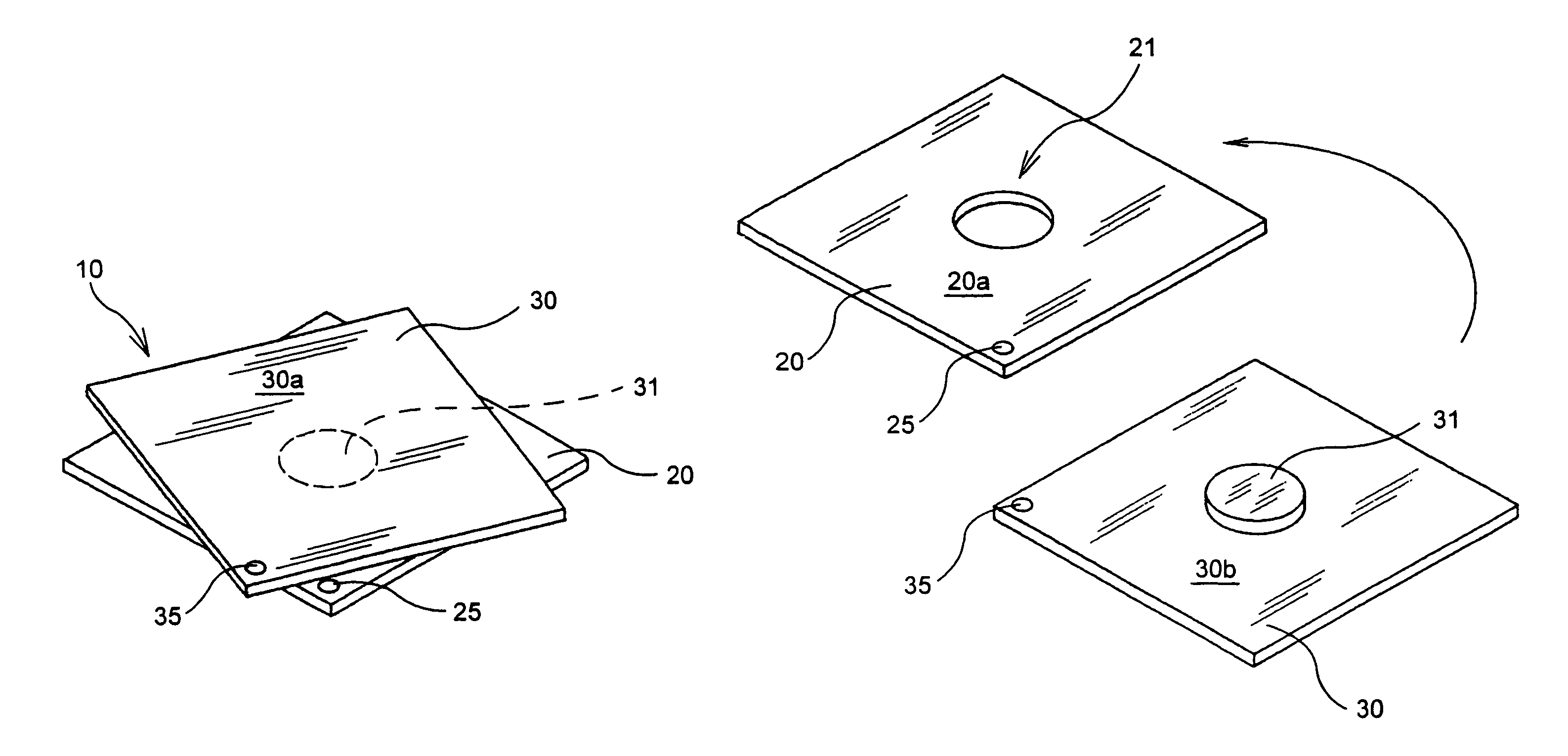
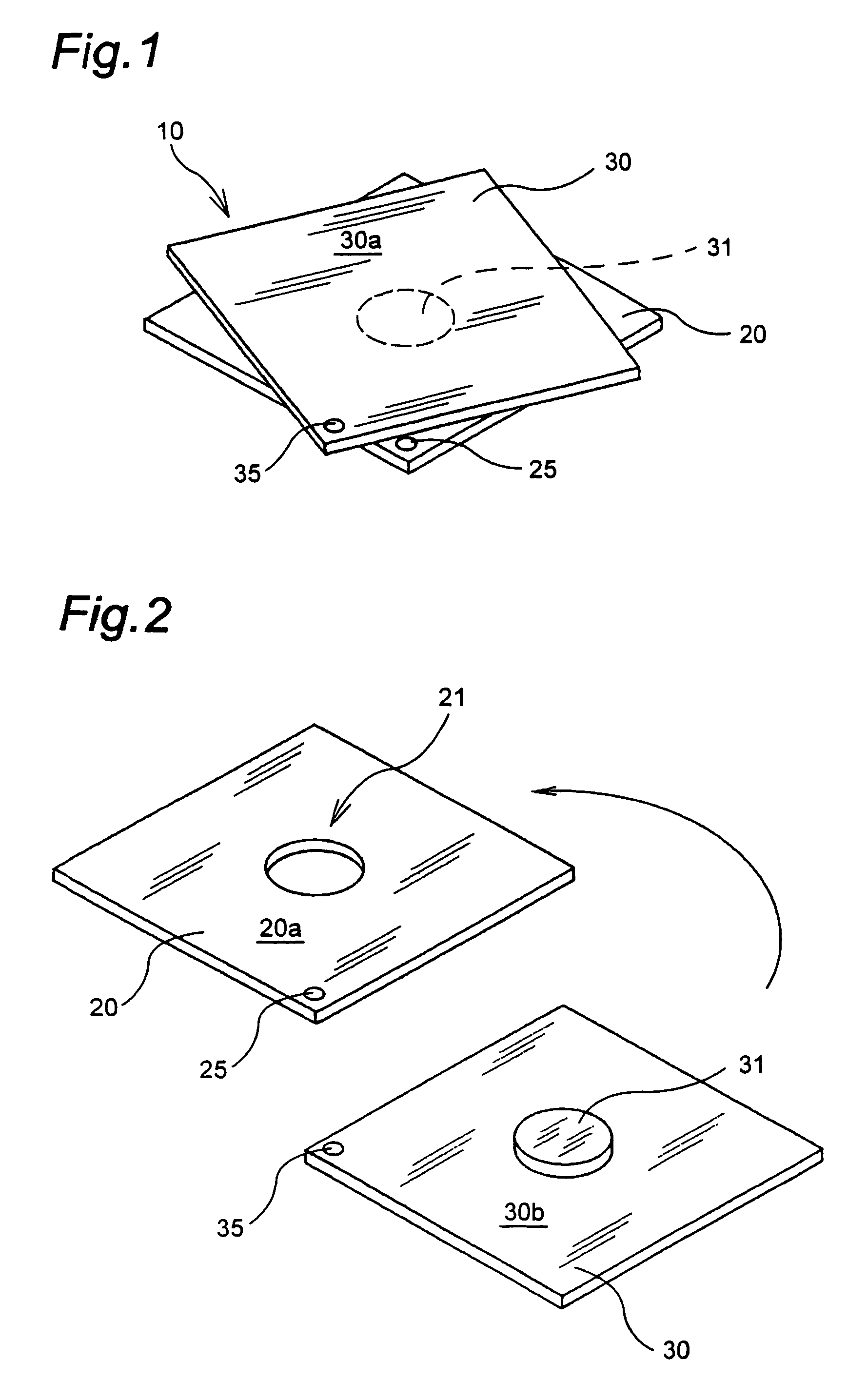
[0023]The embodiments of the present invention will be explained in more detail with reference to the accompanying drawings. FIG. 1 shows a perspective view of a rotary cutting mat 10 according to an embodiment of the present invention.

[0024]The rotary cutting mat 10 comprises a base plate 20 and a rotary mat 30, which are rotatable relative to each other. FIG. 2 shows the base plate 20 and the rotary mat 30, which are illustrated separately from each other for showing the upper surface 20a of the base plate 20, and the reverse side 30b of the rotary mat 30.

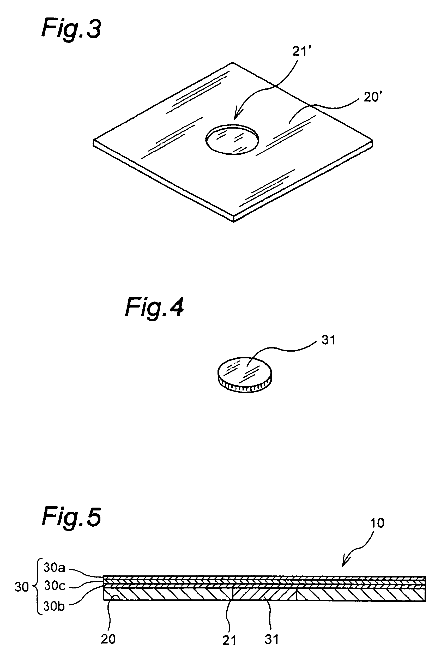
[0025]The base plate 20 has a circular opening 21 formed at its center, and the rotary mat 30 has a cylindrical shaft member 31 at its reverse side 30b. As indicated by the arrow in FIG. 2, the rotary mat 30 is placed on the base plate 20 with its shaft member 31 inserted in the circular opening 21 of the base plate.

[0026]In this way, the rotary mat 30 is simply placed on the base plate 20 without any rivet or the like for connec...


PUM

PropertyMeasurementUnit
pressureaaaaaaaaaa
diametersaaaaaaaaaa
shapeaaaaaaaaaa

Abstract

A rotary cutting mat of the present invention has a base plate and a rotary mat, which can be rotated relative to each other. The rotary mat is provided with a shaft member projected from a reverse side thereof. The base plate is provided with a receiving portion, which rotatably receives the shaft member of the rotary mat. Since the rotary mat is simply placed on the base plate with the shaft member being inserted in the receiving portion, there is no need of a rivet for connecting the rotary mat and the base plate. Thus, the constitution on the mat is simplified and the surface of the mat can be maintained flat without any buried rivet head in the mat.

Description

[0001]This application claims the priority of Japanese Patent Application No. 2004-271195, filed Sep. 17, 2004, the disclosure of which is expressly incorporated by reference herein.BACKGROUND OF THE INVENTION[0002]1. Field of the Invention[0003]The present invention relates to a cutting mat, on which a sheet of paper, cloth or the like is cut with a cutter knife. In particular, the invention relates to a rotary cutting mat, wherein the upper face of the mat can be rotated to improve efficiency of cutting work.[0004]2. Description of the Related Art[0005]A rotary cutting mat having a rotatable upper face is known, for example from Japanese Utility Model Registration No. 3022789.[0006]The rotary cutting mat disclosed in Japanese Utility Model Registration No. 3022789 comprises a base plate and a rotary mat, which are so connected to each other with a rivet, as to be rotatable relative to each other. The reverse side of the base plate is roughened, such that the base plate does not sl...

Claims


Application Information

Patent Timeline
Patent Type & Authority Patents(United States)
IPC IPC(8): B23Q3/00
CPCB26D7/20A47J47/005Y10T83/9312
Inventor OKADA, SHOJI
Owner OLFA
Features
  • R&D
  • Intellectual Property
  • Life Sciences
  • Materials
  • Tech Scout
  • Unparalleled Data Quality
  • Higher Quality Content
  • 60% Fewer Hallucinations
Learn More