Doppler velocity detection device and ultrasonographic device using the same

a velocity detection and ultrasonographic technology, applied in the field of ultrasonographic techniques, can solve the problems of reducing the number of data points input to the velocity detecting/analyzing process unit at a post-stage stage, and affecting the accuracy of the detection. , to achieve the effect of suppressing the influence of clutter signals

Inactive Publication Date: 2011-05-17
HITACHI MEDICAL CORP
View PDF5 Cites 3 Cited by
  • Summary
  • Abstract
  • Description
  • Claims
  • Application Information

AI Technical Summary

Benefits of technology

[0090]According to the present invention, a blood flow can be drawn so as to be distinguished from the motion of an organ. By further utilizing the advantage, in the ultrasonographic device of FIG. 20, a clutter signal detected by the phase rotation detector 13, that is, a signal of the phase rotation velocity of an echo from an organ is input to the scan converter 19, and an image indicative of the motion velocity of the organ or a distribution of the spatial differential can be displayed so as to be superimposed on a blood flow image or by the side of the blood flow image. The usefulness of the configuration will be described by using the case of a hepatic tumor as an example. A neovascular develops in the peripheral portion of a hepatic tumor and blood blow dynamics are different from those of a normal liver around the hepatic tumor. In addition, the hardness of the hepatic tumor is different from that of the normal liver, so that motion of the tissues of the hepatic tumor is also different from that of the periphery. Therefore, display of not only a blood flow image but also variations according to sites of the motion velocity in the organ is very useful to diagnosis of a hepatic tumor.

Problems solved by technology

The process, however, has the following drawbacks.1) In the case of using a low-frequency cutoff filter to which N1 time-series data points are input, the number of data points input to a velocity detecting / analyzing process unit at a post stage is reduced by (N1−1).2) A filter of a sharp cutoff characteristic is not easily obtained.
A cutoff characteristic to eliminate the low frequency component is necessary while maintaining an echo signal from a moving reflector, so that the above-described point 2) becomes a problem.
However, when the velocity of a moving object is detected and analyzed by a conventional method of the kind expressed by the above equation (1) in a later stage of the process performed by the polynomial regression filter, a problem occurs such that a velocity computation error around the cutoff frequency is larger as compared with that in a conventional filter.
Consequently, in the case where precision of velocity as a result of the detection / analysis is requested to some extent, a signal of a moving object in a frequency band of a portion extended to a low band cannot be used due to the sharp cut off characteristic of the polynomial regression filter.

Method used


Image

  • Doppler velocity detection device and ultrasonographic device using the same
  • Doppler velocity detection device and ultrasonographic device using the same
  • Doppler velocity detection device and ultrasonographic device using the same

Examples


Embodiment Construction

[0073]Embodiments of the present invention will be described in detail hereinbelow with reference to the drawings.

[0074]FIG. 19 is a block diagram showing a typical example of an ultrasonographic device with a blood flow drawing function constructed to carry out the present invention. Elements constructing an ultrasonic probe 1 are connected to a transmission beam former 3 and a reception beam former 10 via a change-over switch group 2. The transmission beam former 3 generates a signal which becomes an ultrasonic pulse having directivity when transmitted via the elements by using a waveform selected by a transmission waveform selector 4 and read from a transmission waveform memory 5 under control of a transmission / reception sequence controller 6. The signal is converted to an ultrasonic pulse by each of the elements of the ultrasonic probe1 and the ultrasonic pulse is transmitted to a living body. An ultrasonic echo signal reflected or scattered in the living body and returned to th...


PUM


Abstract

The present invention realizes a Doppler velocity detecting technique capable of performing velocity detection and analysis with a suppressed error while excellently distinguishing a clutter signal, and provides an ultrasonographic device using the technique. In a Doppler velocity detection device comprising means for transmitting / receiving pulse waves to / from a subject a plurality of times, and velocity analyzing means for analyzing a velocity of a moving reflector in the subject on the basis of a reception echo signal, the velocity analyzing means obtains a complex expansion coefficient by linearly connecting an expansion coefficient of an even-numbered degree term and an expansion coefficient of an odd-numbered degree term which is different from the even-numbered degree term by one degree, derived when reception echo time-series signals obtained by arranging reception echo signals of equal lapse time from pulse transmission times in order of the transmission times are expanded as components of a Legendre polynomial starting from the 0th degree, by using an imaginary unit as a coefficient, and obtains a signed velocity signal of a moving reflector in the subject on the basis of-the ratio between the magnitude of each complex expansion coefficient and the magnitude of an interval between the complex expansion coefficients.

Description

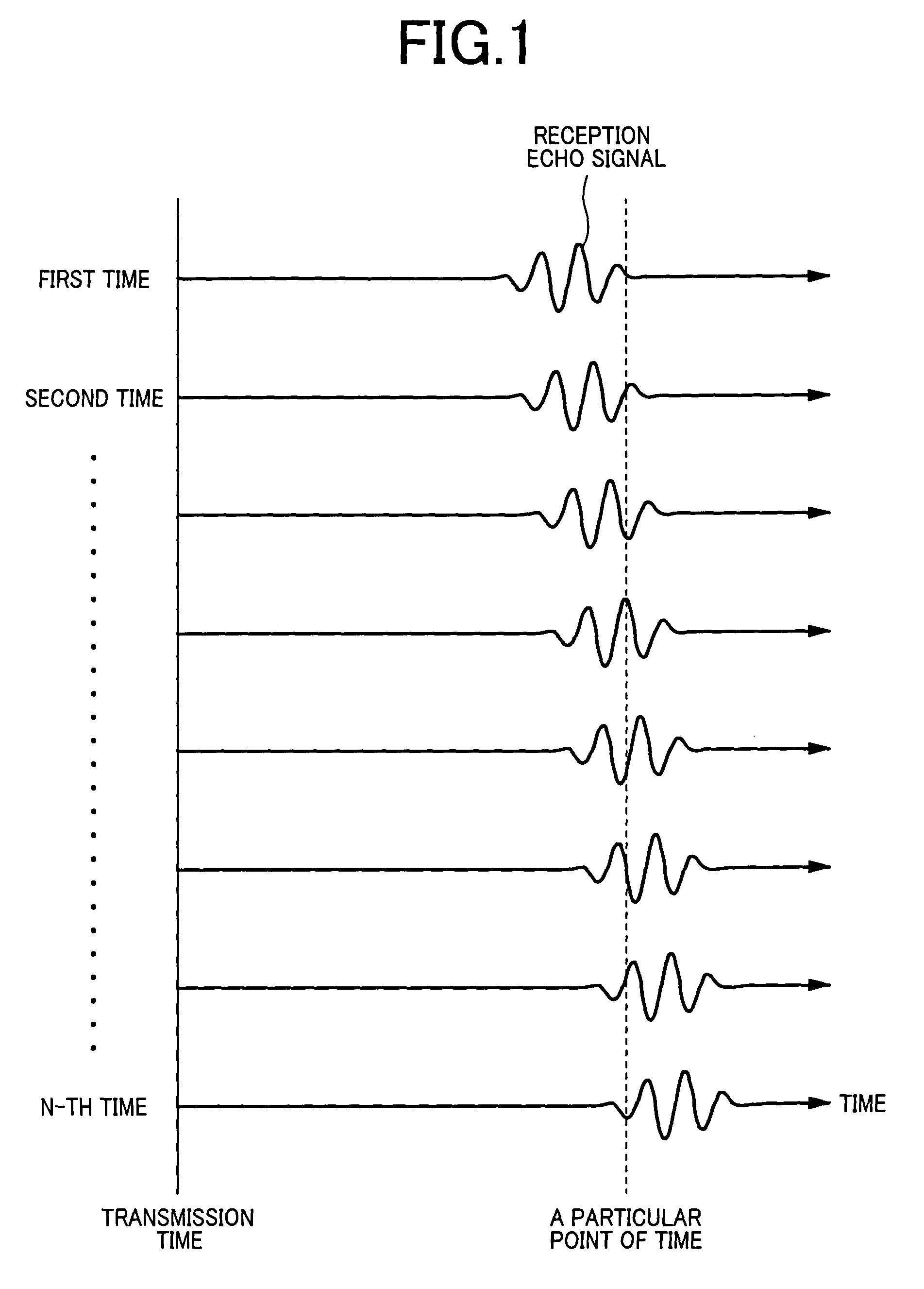
TECHNICAL FIELD[0001]The present invention relates to an ultrasonographic technique such as an ultrasonic Doppler blood flowmeter or a blood flow drawing device for medical diagnosis that detects a moving reflector such as a blood flow in a living body by transmitting / receiving ultrasonic waves to / from a living body and displays a distribution of velocity and a spatial distribution of velocity.BACKGROUND ART[0002]A pulse Doppler device transmits / receives waves such as pulse ultrasonic waves or electromagnetic waves to / from an object and analyzes time-series signals obtained by arranging signals of a particular point of time with equal lapse time from pulse transmission times of a plurality of received echo signals as shown in FIG. 1 in order of the transmission times, thereby obtaining information such as velocity of a moving object. The most common signal processing method performs quadrature detection on the reception signals and analyzes them as complex time-series signals. Such ...

Claims


Application Information

Patent Timeline
Patent Type & Authority Patents(United States)
IPC IPC(8): A61B8/00G01S15/89
CPCG01S15/8981G01S15/8977
Inventor UMEMURA, SHIN-ICHIROAZUMA, TAKASHIHAYASHI, TETSUYA
Owner HITACHI MEDICAL CORP
Why Eureka
Try Eureka