Single stage electrostatic precipitator

a precipitator and single-stage technology, applied in the field of electrostatic precipitators, can solve the problems of filter losing the ability to collect particulate matter, and achieve the effect of easy assembly and easy testing for proper assembly

Inactive Publication Date: 2011-05-17
GALE ROGER
View PDF19 Cites 12 Cited by
  • Summary
  • Abstract
  • Description
  • Claims
  • Application Information

AI Technical Summary

Benefits of technology

[0006]It is another object of this invention to provide an improved electrostatic filter, which may be easily assembled.
[0007]It is a further object of this invention to provide an improved electrostatic filter, which may be easily tested for proper assembly.
[0009]It is yet another object of this invention to provide an improved electrostatic filter, which may be installed with cost savings.

Problems solved by technology

While the electrostatic filter has evolved over the years there remain two basic operational problems.
When this happens, the filter loses the ability to collect particulate for the time that the ioniser is discharged.

Method used


Image

  • Single stage electrostatic precipitator
  • Single stage electrostatic precipitator
  • Single stage electrostatic precipitator

Examples


Embodiment Construction

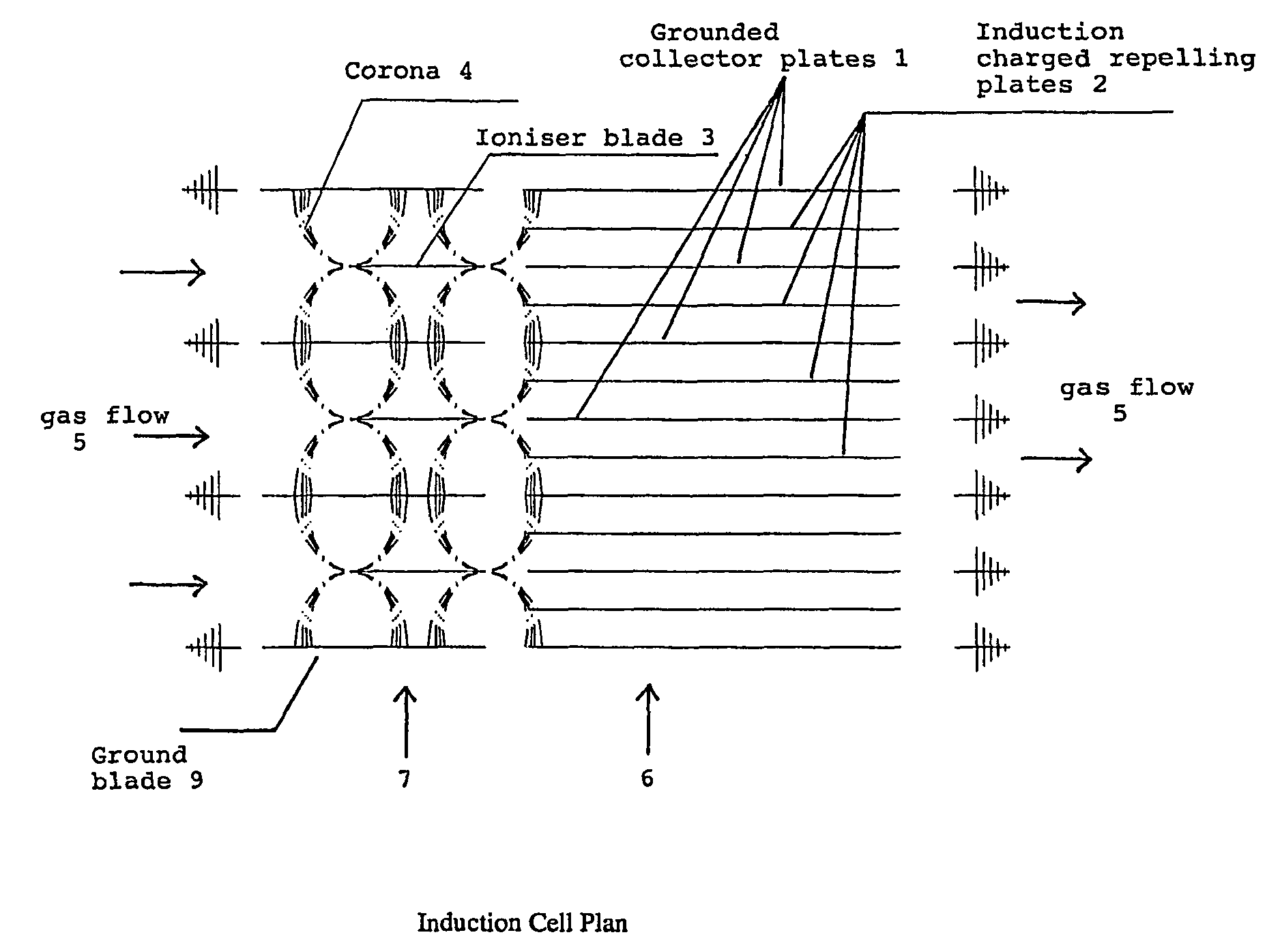
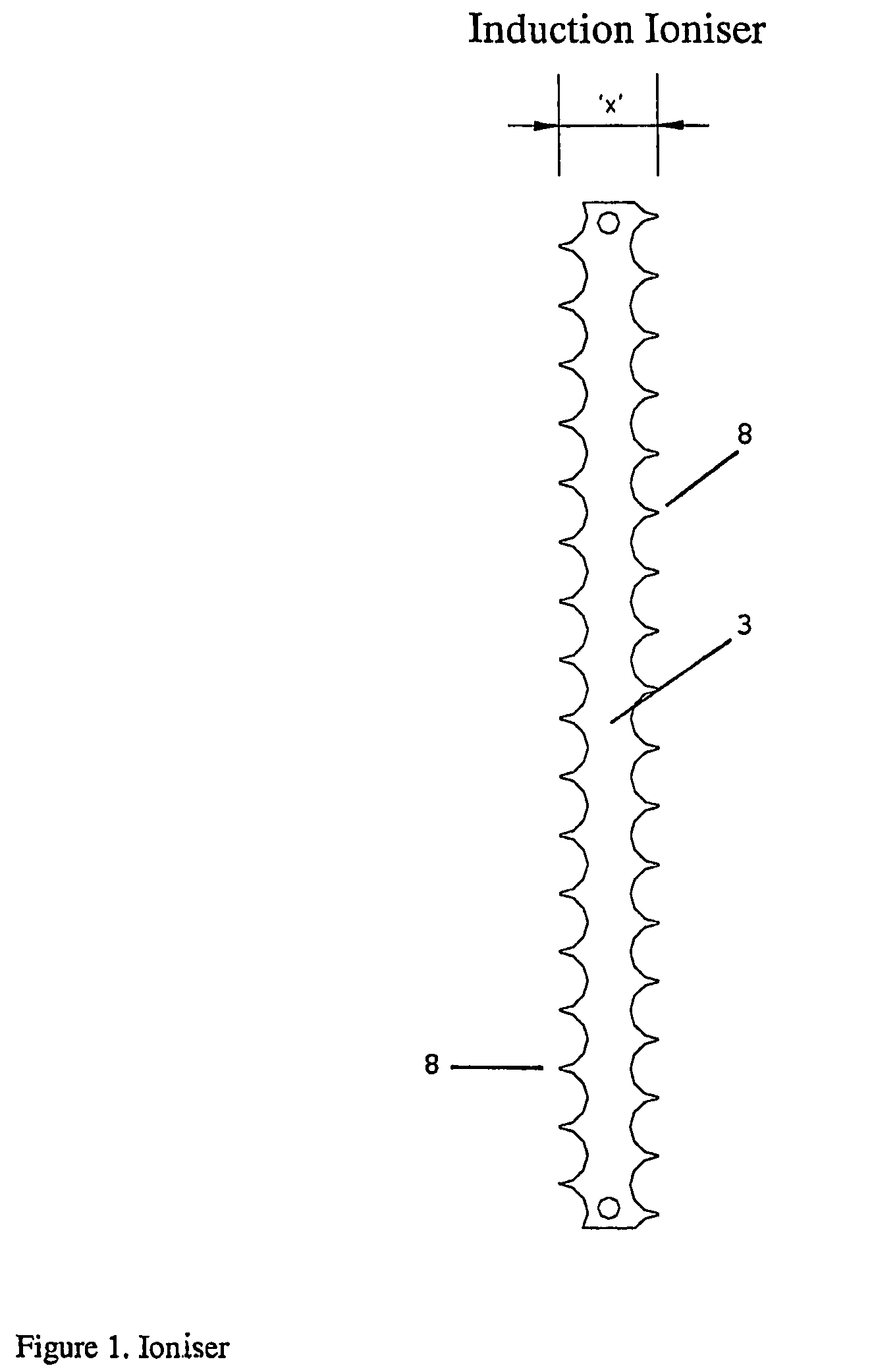
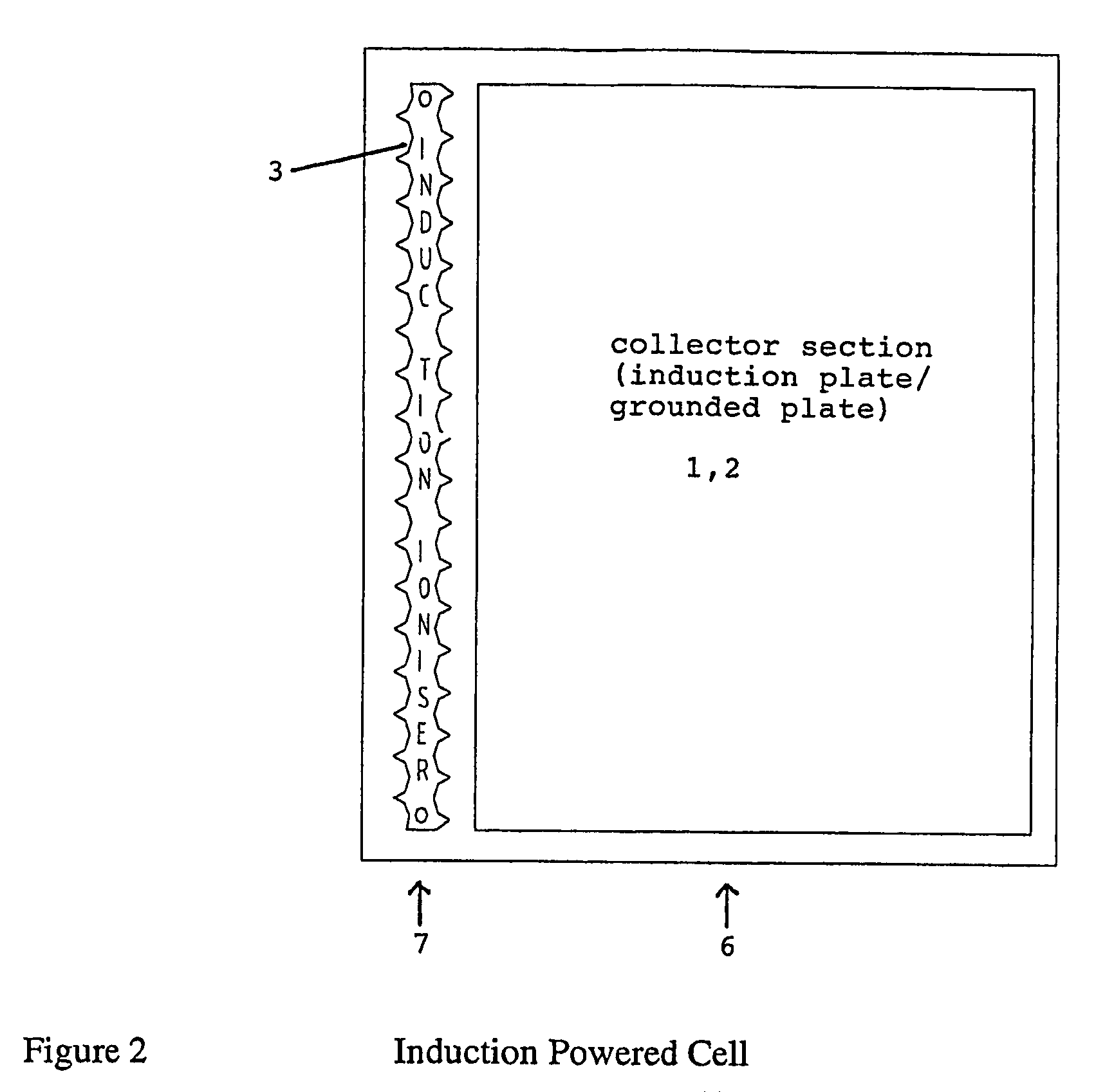
[0016]Referring to FIG. 3, which shows a preferred embodiment of the invention schematically, the electrostatic filter utilises a series of parallel flat conduction plates 1, 2 and flat ‘saw tooth’ ioniser blades 3 (with sharp teeth 8) standing parallel to and in front of the conduction plates 1,2. The flat ‘saw tooth’ ioniser blades 3 are placed so that they are lying in the same plane as some of the conduction plates 1,2. The ioniser blades 3 are charged to a high potential typically greater than 11000 volts DC. The ioniser blades 3 have such a width, in the direction of gas flow 5, that they induce a voltage in some 2 of the parallel conduction plates. The parallel conduction plates 2 are not electrically connected to a power supply. The ioniser blades 3 and complementary ground blades 9 constitute together an ioniser section 7. The ground blades 9 are arranged substantially between and parallel to the ioniser blades 3 for assisting in providing a corona discharge 4 from the ioni...


PUM


Abstract

In an electrostatic precipitator for filtering particulate matter from a gas, a fan (10) draws the gas (5) through an ioniser section (7) and a collector section (6). Ioniser blades (3) with sawtooth spikes (8) create a corona discharge (4) when charged to a high voltage, so that gas-borne particles are charged when passing through the corona area. The collector section (6) consists of a set of metallic plates (1, 2) of which every other plate (1) is connected to ground, while the remaining plates (2) receive a charge by induction from the ioniser blades (3), and act as repeller plates, pushing charged particles in the gas flow (5) over to the grounded plates (1).

Description

[0001]This application is the national stage of PCT Application No. PCT / NO2006 / 000378, filed on Oct. 17, 2006.TECHNICAL FIELD[0002]The present application relates to apparatus for filtering particulate matter from gasses and more particularly to electrostatic filters which are adapted to remove particles by charging gas-borne particles by means of an ioniser arrangement and thereafter precipitating the charged particles in a collector section with differently charged parallel plates. Typically these filters will be used to remove particulate from air streams.BACKGROUND ART[0003]The prior art includes filters using the principle of electrostatics for removing particles from various gasses; normally air, at velocities up to 10 m / s. The principle here employed is as follows. The air is propelled through an electric field where particles in the air receive an electric charge. The charged particles move into a collector section where each alternate plate is charged with the same polarity...

Claims


Application Information

Patent Timeline
Patent Type & Authority Patents(United States)
IPC IPC(8): B03C3/08B01DB03C3/41
CPCB03C3/08B03C3/41B03C2201/10B03C3/12
Inventor GALE, ROGER
Owner GALE ROGER
Why Eureka
Try Eureka