Display drive apparatus in which display pixels in a plurality of specific rows are set in a selected state with periods at least overlapping each other, and gradation current is supplied to the display pixels during the selected state, and display apparatus

a display apparatus and drive control technology, applied in the direction of static storage, electrical analogies, instruments, etc., can solve the problems of deterioration of display image quality, inability to perform appropriate gradation control, and inability to stably realize desired light emission characteristics for a long period in time, so as to achieve excellent display panel high definition

Active Publication Date: 2011-05-17
SOLAS OLED LTD
View PDF33 Cites 66 Cited by
  • Summary
  • Abstract
  • Description
  • Claims
  • Application Information

AI Technical Summary

Benefits of technology

[0025]In a display drive apparatus which drives display pixels of a display panel based on display data and a display apparatus comprising this display drive apparatus, the present invention has an advantage that occurrence of an insufficient write state in an operation of writing a gradation current in each display pixel can be suppressed and the high definition of the display panel can be excellently realized.

Problems solved by technology

Thus, the pixel drive circuit has a problem that desired light emission characteristics (display with a predetermined luminance gradation) cannot be stably realized for a long period in time.
Alternatively, when each display pixel is finely formed in order to realize the high definition of the display panel, irregularities in operation characteristics (a current between the source and the drain of the transistor and others) of a switch element constituting the pixel drive circuit become large, and hence an appropriate gradation control cannot be performed.
Accordingly, the pixel drive circuit has a drawback that generation of irregularities in light emission characteristics of each display pixel results in deterioration of a display image quality.
However, the pixel drive circuit adopting the current specification mode has the following problems.
The write operation with respect to each display pixel cannot be completed in a preset write time, and there occurs a so-called insufficient write state in which a stable state (a saturation state) is not reached.
As a result, there is a display pixel which cannot emit a light with an appropriate luminance gradation corresponding to display data, resulting in deterioration in a display image quality.
Additionally, when the number of scanning lines arranged on the display panel is increased and a selection period (i.e., a write time) of each scanning line is set short in order to realize the high definition of the display panel, the sufficient write operation with respect to each display pixel cannot be performed as a current value of the gradation current is reduced, and the insufficient write state is generated, which leads to deterioration in a display image quality or a restriction in high definition of the display panel.

Method used


Image

  • Display drive apparatus in which display pixels in a plurality of specific rows are set in a selected state with periods at least overlapping each other, and gradation current is supplied to the display pixels during the selected state, and display apparatus
  • Display drive apparatus in which display pixels in a plurality of specific rows are set in a selected state with periods at least overlapping each other, and gradation current is supplied to the display pixels during the selected state, and display apparatus
  • Display drive apparatus in which display pixels in a plurality of specific rows are set in a selected state with periods at least overlapping each other, and gradation current is supplied to the display pixels during the selected state, and display apparatus

Examples


first embodiment

of Display Apparatus

[0072]A schematic configuration of a display apparatus to which a display drive apparatus according to the present invention can be applied will be first described.

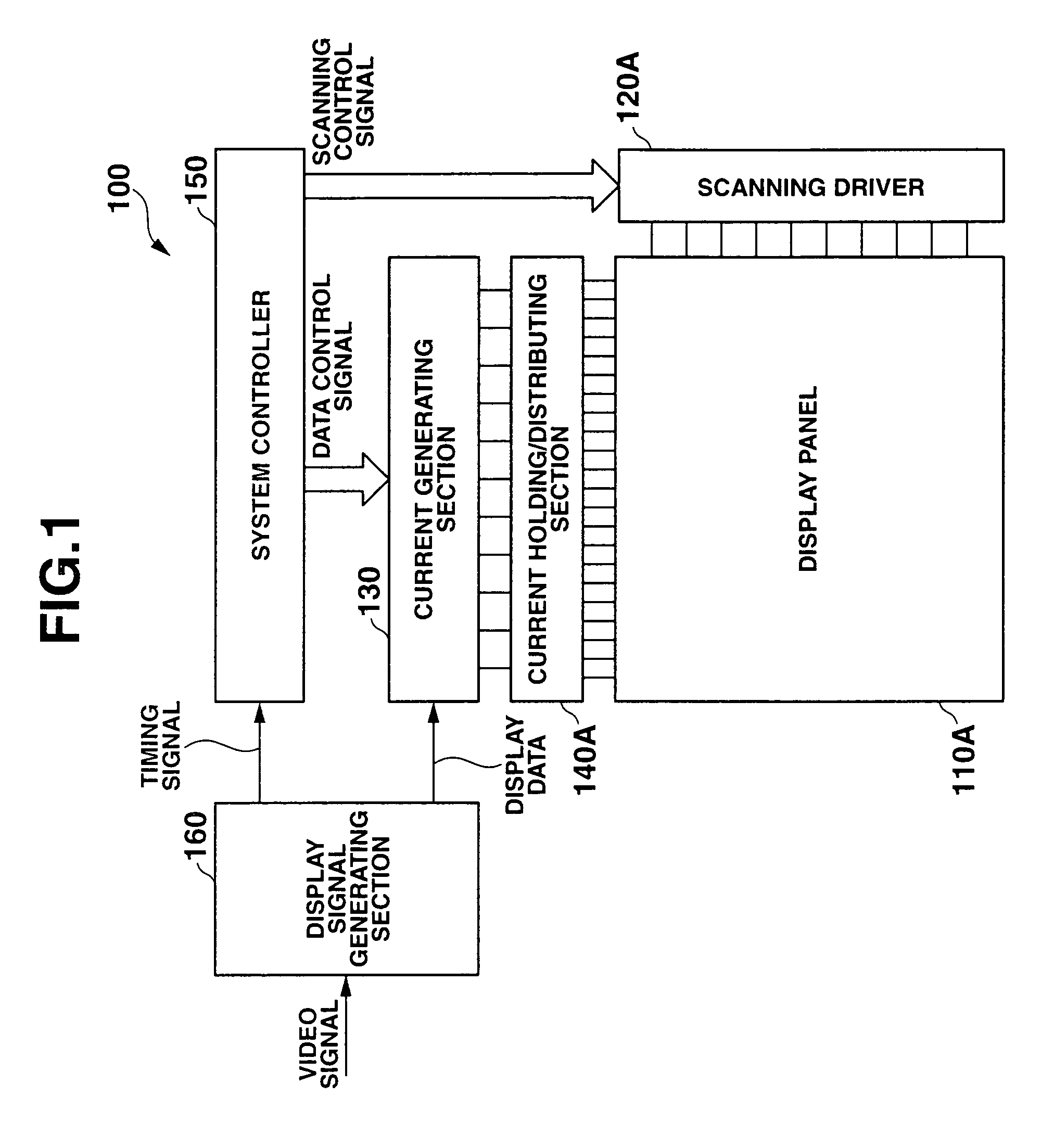
[0073]FIG. 1 is a schematic block diagram showing an entire configuration of a display apparatus according to an embodiment of the present invention.

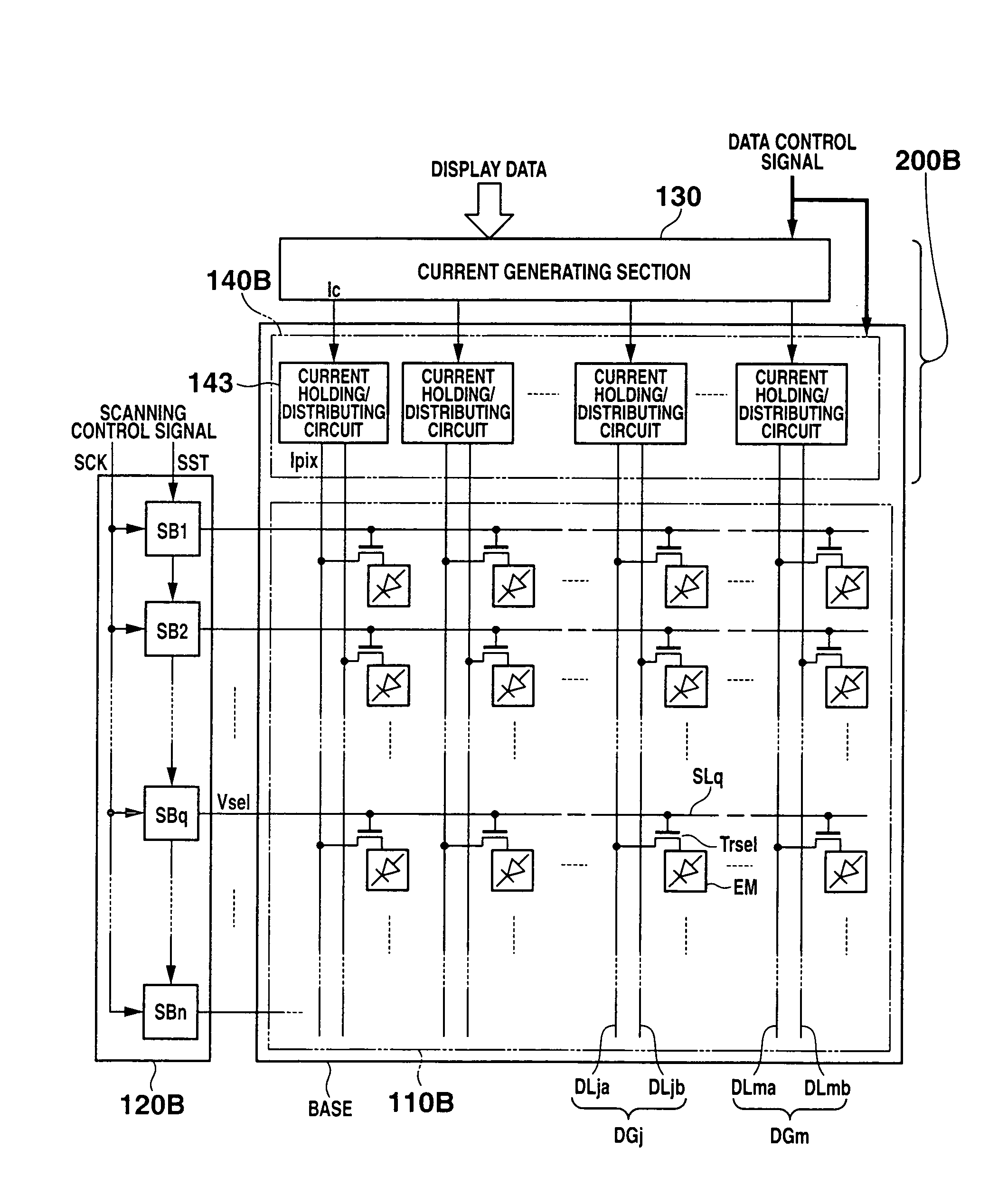
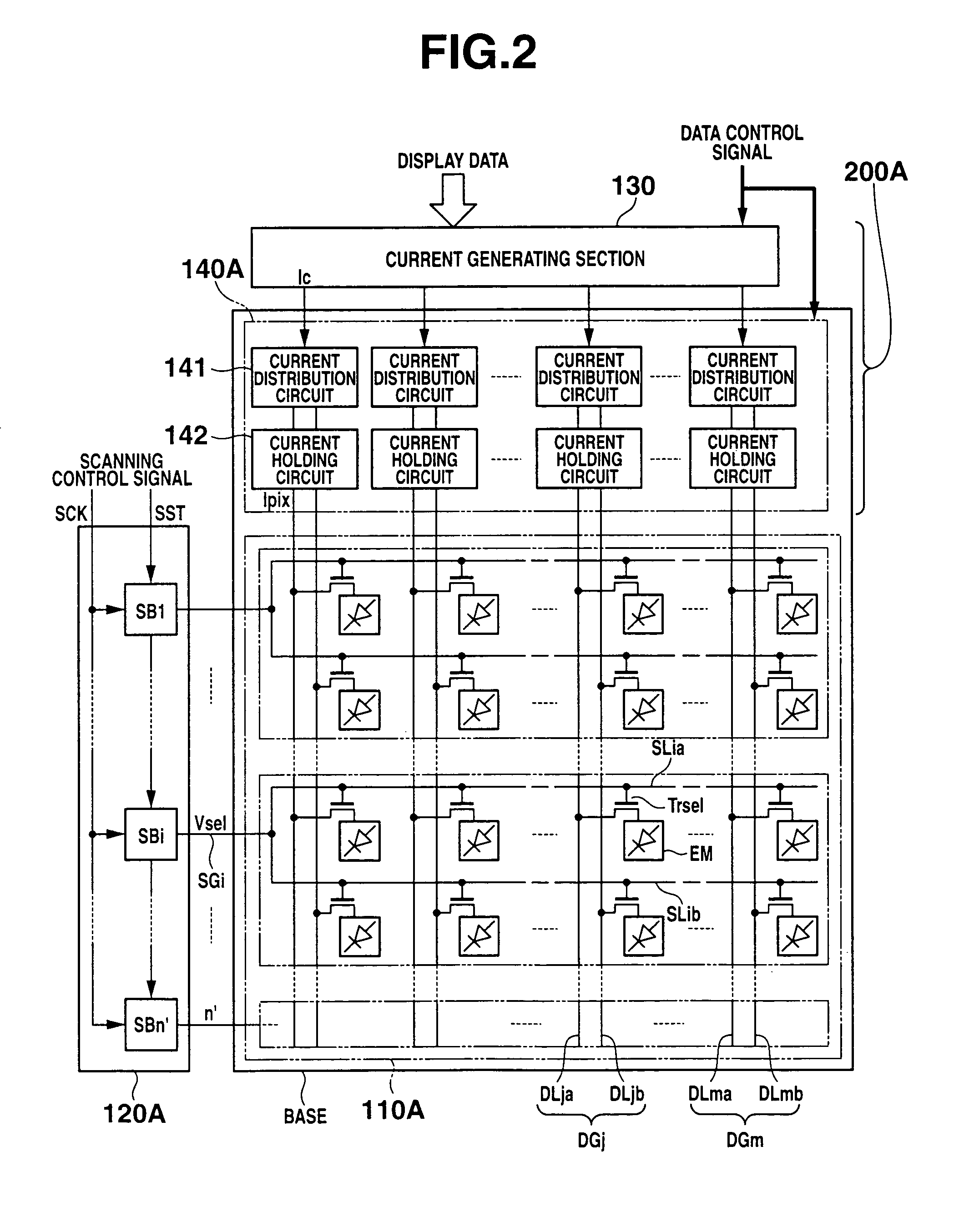
[0074]FIG. 2 is a structural view showing a primary part of the display apparatus according to this embodiment.

[0075]As shown in FIG. 1, a display apparatus 100 according to the present invention roughly has a display panel 110A, a scanning driver (a selection circuit) 120A, a current generating section (a gradation signal generation circuit) 130, a current holding / distributing section (a current write circuit) 140A, a system controller 150 and a display signal generating section 160.

[0076]As shown in FIG. 2, the display panel 110A substantially has a plurality of display pixels EM which are two-dimensionally arranged (n rows×m columns) and connected to se...

second embodiment

of Display Apparatus

[0160]A second embodiment of a display apparatus according to the present invention will now be described with reference to the accompanying drawings.

[0161]FIG. 9 is a structural view showing a primary part of a second embodiment of a display apparatus according to the present invention.

[0162]Here, structures equal to those in the first embodiment are denoted by equal or like reference numerals, thereby eliminating the explanation thereof.

[0163]The display apparatus according to the abovementioned first embodiment comprises: the display panel in which each scanning line group SGi corresponding to a plurality of rows and each data line group DGj consisting of a plurality of data lines corresponding to the plurality of rows are arranged; and peripheral circuits (the scanning driver and the signal driver comprising the current generating section and the current holding / distributing section) corresponding to the display panel. The display apparatus according to the s...


PUM


Abstract

A display drive apparatus includes a selection circuit which sets display pixels in a plurality of specific rows of the display panel in a selected state with periods at least overlapping each other. A gradation signal generation circuit generates a gradation signal which controls a luminance gradation of each display pixel based on the display data and sequentially supplies the generated gradation signal in time series. A plurality of signal distribution circuits sequentially distribute the gradation signal supplied by the gradation signal generation circuit in accordance with the plurality of display pixels in each column at the timing of time-series supply. A plurality of current holding circuits individually hold the distributed gradation signal and simultaneously supply as the gradation current a current having a current value based on the held gradation signal to the display pixels in the plurality of specific rows.

Description

CROSS-REFERENCE TO RELATED APPLICATIONS[0001]This application is based upon and claims the benefit of priority from prior Japanese Patent Applications No. 2004-160140, filed May 28, 2004; and No. 2004-266441, filed Sep. 14, 2004, the entire contents of both of which are incorporated herein by reference.BACKGROUND OF THE INVENTION[0002]1. Field of the Invention[0003]The present invention relates to a display drive apparatus, a display apparatus and a drive control method thereof, and more particularly to a display drive apparatus which can be applied to a display panel having a plurality of display pixels arranged therein, each display pixel comprising a current controlled type light emitting element which emits a light with a predetermined luminance gradation by supplying a current corresponding to display data thereto, and a display apparatus comprising the display drive apparatus, and a drive control method thereof.[0004]2. Description of the Related Art[0005]There has been conven...

Claims


Application Information

Patent Timeline
Patent Type & Authority Patents(United States)
IPC IPC(8): G09G3/30G09G3/32G09G3/36G11C27/02
CPCG09G3/325G11C27/028G09G3/3266G09G3/3283G09G3/3648G09G2300/0426G09G2300/0866G09G2310/0205G09G2310/0218G09G2310/027G09G2310/0297G09G2300/0842G09G3/3225G09G3/20G09G3/30G09G3/32
Inventor SHIRASAKI, TOMOYUKIOZAKI, TSUYOSHIOGURA, JUN
Owner SOLAS OLED LTD
Why Eureka
Try Eureka