Matrix converters

a matrix converter and converter technology, applied in the field of matrix converters, can solve the problems of large over-voltage, severe damage to the matrix converter, and lack of natural freewheel paths

Inactive Publication Date: 2011-05-17
GE POWER CONVERSION
View PDF14 Cites 12 Cited by
  • Summary
  • Abstract
  • Description
  • Claims
  • Application Information

AI Technical Summary

Benefits of technology

[0017]It will readily appreciated that a matrix converter which is configured only to operate in generating mode to feed dc link power from a generator into a power grid or supply network could be considered to be identical to a current source inverter. The significance of the present invention is that the matrix converter is able to regulate bi-directional power flow, whilst retaining a uni-directional dc link voltage, i.e. its dc current flow is bidirectional. The conventional current source inverter is able to regulate bi-directional power flow by allowing its dc terminal voltage to reverse, i.e. its dc current flow is uni-directional. The uni-directional dc voltage in the matrix converter according to the present invention is specifically used to permit the freewheel path to provide benefits.
[0021]The addition of the freewheel path represents a significant departure from conventional matrix converters and provides a “fifth state” in addition to the three states that are provided by connecting each of the ac voltage lines to both of the dc voltage lines in either polarity, and the fourth state that is provided by connecting both of the dc voltage lines to the same ac voltage line. In the “fifth state” all of the matrix switches are operated to be open such that the dc voltage lines are not connected to any of the ac voltage lines. Instead of causing a large over-voltage, the inductive current load is allowed to flow through the freewheel path. If the matrix converter is used for motoring applications, where the dc output voltage is pulse width modulated to a lower level, the “fifth state” may be used for a greater proportion of the time and this results in a significant reduction in dissipation and an increase in efficiency compared to conventional matrix converters because the freewheel path has lower conduction losses. Another advantage of the “fifth state” is that the pulse width modulation common mode voltage is reduced.
[0027]The power converter may further include a switching aid network (snubber) connected between the dc voltage lines. The snubber may be of any suitable type depending on the particular application. For example, the snubber may be of the capacitor resistor type. Any switching voltage transient that is experienced across the terminals of the freewheel path is also experienced by any of the semiconductor devices that form part of the first, second, third, fourth, fifth and sixth switches. Therefore, only a single snubber is needed. This simplifies the design of the power converter and improves its efficiency.

Problems solved by technology

One of the major problems with conventional matrix converters is the lack of natural freewheel paths.
If an output line is connected to two or more of the input lines at the same time then this will cause a short circuit and the resulting large current may cause severe damage to the matrix converter, or even destroy it.
On the other hand, if an output line is not connected to any of the input lines then there is no path for the inductive current load and this will cause a large over-voltage.
It will be appreciated that currently available semiconductor switches cannot be switched on and off with the necessary degree of precision and it is therefore impossible to prevent short and open circuits on the output lines of the matrix converter without using some orderly form of current commutation.

Method used


Image

  • Matrix converters
  • Matrix converters
  • Matrix converters

Examples


Embodiment Construction

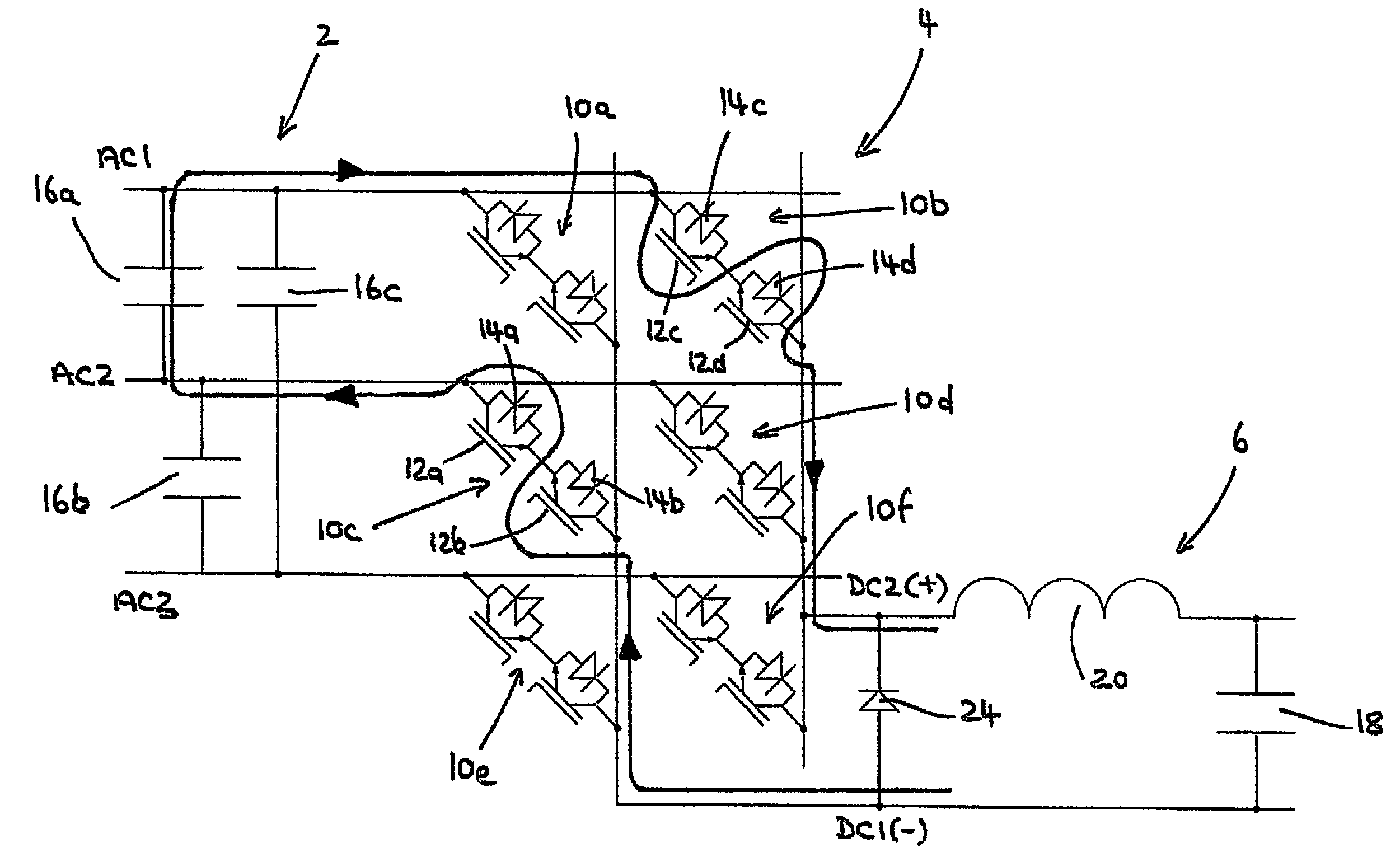
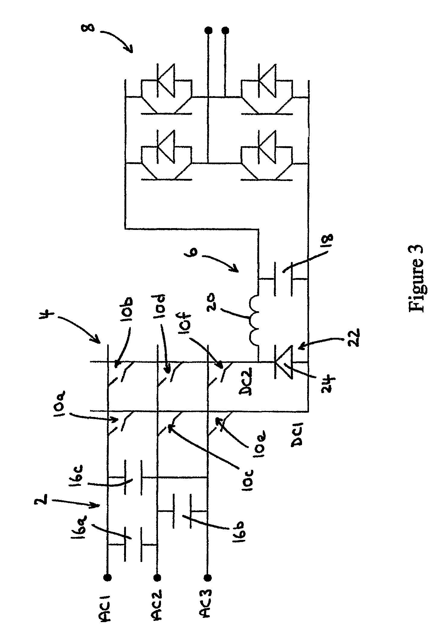
[0058]The topology and operation of a matrix converter according to the present invention will now be explained with references to FIG. 3 to 6. FIG. 3 shows a basic two-stage power converter including an ac line filter 2, a matrix converter 4, a dc-link filter 6 and a voltage source inverter 8. Any other suitable type of inverter (such as a current source inverter, for example) can be used in place of the voltage source inverter 8 depending on the particular application. The voltage source inverter 8 of the power converter may be implemented using the ALSTOM VDM25000 product, available from ALSTOM Power Conversion Limited, Marine and Offshore Division, Boughton Road, Rugby, CV21 IBU, United Kingdom.

[0059]The matrix converter 4 includes three ac voltage lines labelled AC1, AC2 and AC3, and two dc voltage lines labelled DC1 and DC2. Six switch assemblies 10a to 10f allow any of the ac voltage lines AC1, AC2 and AC3 to be connected to any of the dc voltage lines DC1 and DC2. For exampl...


PUM


Abstract

A matrix converter that can be used as part of a two-stage power converter has three ac three ac voltage lines AC1, AC2 and AC3 and two dc voltage lines DC1 and DC2. An array of six semiconductor switches 10a to 10f are arranged such that each of the three ac voltage lines AC1, AC2 an AC3 can be connected to one of the two dc voltage lines DC1 and DC2 when the associated switch is closed. A freewheel path is provided between the two dc voltage lines DC1 and DC2, which provides a fifth state of operation when all the switches 10a to 10f are open.

Description

FIELD OF THE INVENTION[0001]The present invention relates to matrix converters, and in particular to matrix converters that can be used to form the first stage of a two-stage power converter, or used as a single or multi-stage power supply. The two-stage power converter can be used to interface a variable speed drive to a supply network, for example. The matrix converter can also be used to feed a dc load or to condition power that is fed back to an ac power grid or supply network.BACKGROUND OF THE INVENTION[0002]Matrix converters are becoming an increasingly popular way of providing direct power conversion for variable speed drives and power supplies. In its most basic form, a matrix converter consists of an array of switches that are arranged such that any of a number of input lines can be connected to any of a number of output lines in a predetermined configuration. A conventional single-stage matrix converter is shown in FIG. 1. The matrix converter has three input lines labelle...

Claims


Application Information

Patent Timeline
Patent Type & Authority Patents(United States)
IPC IPC(8): H02M7/757H02M7/81H02M7/162H02M7/219
CPCH02M7/219H02M7/162H02M7/217
Inventor CRANE, ALLAN DAVID
Owner GE POWER CONVERSION
Why Eureka
Try Eureka