Time delay estimation

a time delay estimation and time interval technology, applied in the field of time delay estimation, can solve the problems of insufficient accuracy, prohibitively expensive time delay estimation methods, and inability to accurately detect such small time intervals,

Active Publication Date: 2011-05-17
VOXIS
View PDF15 Cites 96 Cited by
  • Summary
  • Abstract
  • Description
  • Claims
  • Application Information

AI Technical Summary

Problems solved by technology

Conventional methods of time delay estimation are either prohibitively expensive or unable to accurately detect such small time intervals.
However, as discussed above, these methods fail to provide sufficient accuracy for short time interval estimation and thus cannot provide a quality distance measurement.
However, only a small part of the pulse energy is used in such an approach.
This approach also compromises system accuracy by separately introducing a calibration pulse into each channel.
However, the Nutt interpolator cannot measure pulse widths wider than the resolution of the filter used and information is lost.
Accordingly, such a method cannot properly account for the increased resolution accuracy required in modern time delay estimation.

Method used


Image

  • Time delay estimation
  • Time delay estimation
  • Time delay estimation

Examples


Embodiment Construction

[0020]At least one embodiment of the present invention provides techniques for measuring the time between two optical pulses (e.g., a start pulse and a stop pulse) that relate to the transit time between a measurement instrument and a distant object. Of course, this may be extended to measure or estimate the time between any two events using the inventive techniques described herein. When applied to laser scanning, optical pulses are converted into an electrical signal to enable an electronic device to make an estimate of the time differential.

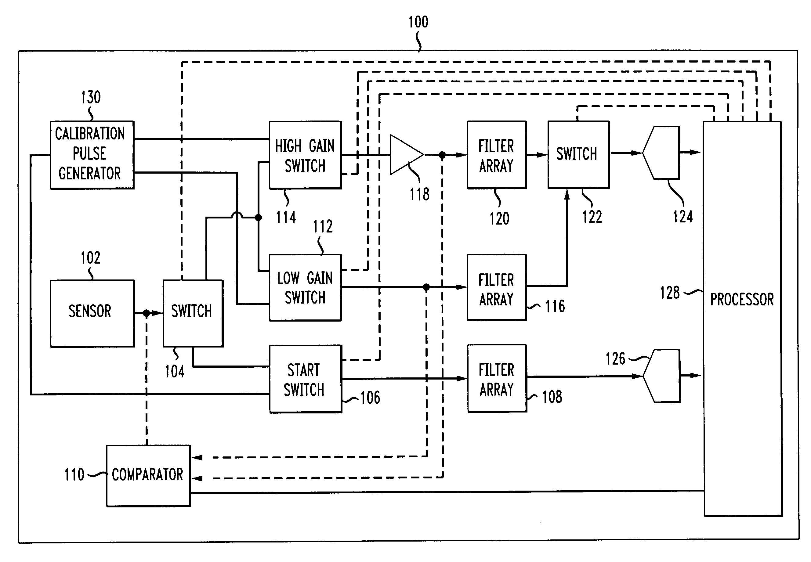
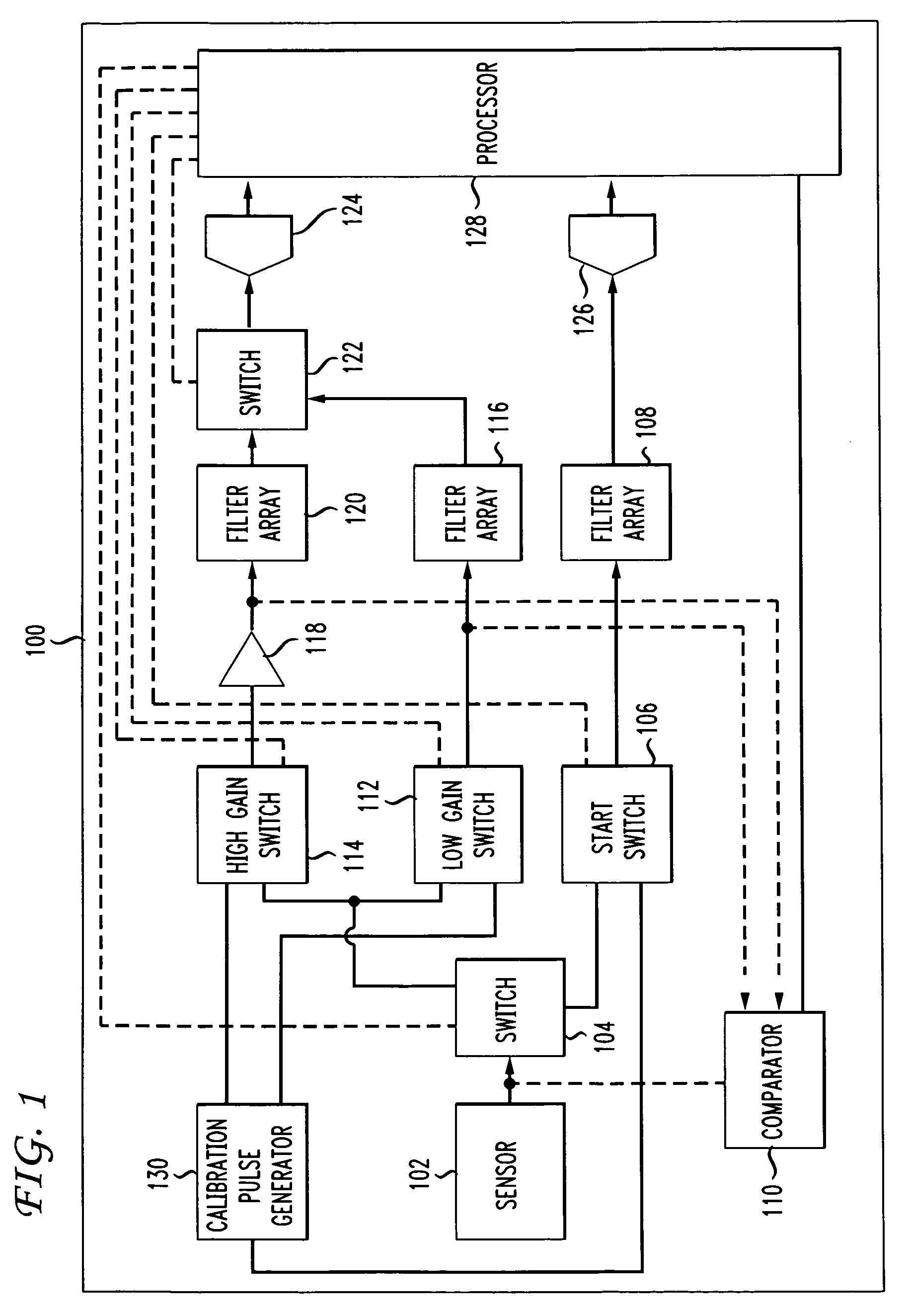
[0021]FIG. 1 depicts a time delay estimation circuit 100 according to an embodiment of the present invention. Though described herein as a general circuit with specific reference to components of that circuit, one of skill in the art will recognize that the functions of time delay estimation circuit may be performed by any appropriate combination of electrical and / or electromechanical devices.

[0022]Circuit 100 includes sensor 102, which receiv...


PUM


Abstract

A time differential is estimated between a plurality of signals by determining a filter response of a first electrical signal with a first filter array, determining a filter response of a second electrical signal with a second filter array, and determining, based at least on the filter response of the first electrical signal and the filter response of the second electrical signal, a time differential between the first electrical signal and the second electrical signal. A first optical signal is converted into the first electrical signal and a second optical signal is converted into the second electrical signal. The filter response of the first electrical signal and the filter response of the second electrical signal are sampled and the time differential between the first electrical signal and the second electrical signal is determined based at least on the sampled filter response of the first electrical signal and the sampled filter response of the second electrical signal.

Description

[0001]This application claims the benefit of U.S. Provisional Application No. 60 / 994,639 filed Sep. 20, 2007 which is incorporated herein by reference.BACKGROUND OF THE INVENTION[0002]The present invention relates generally to time delay estimation and more particularly to circuits for time delay estimation in laser scanning.[0003]Increasing complex systems require increasingly accurate and fine-grained time delay estimation. For example, some laser scanning systems measure a time delay between a sent and received laser pulse to determine the distance to an object. The time delay between the sending of the pulse and the receiving of the reflected pulse is very small and must be measured with great accuracy—on the order of less than 10 nanoseconds—in order to properly determine the desired distance measurement. Conventional methods of time delay estimation are either prohibitively expensive or unable to accurately detect such small time intervals.[0004]In a laser scanning system, the...

Claims


Application Information

Patent Timeline
Patent Type & Authority Patents(United States)
IPC IPC(8): G01R25/00G01S7/4861G01S7/4865G01S17/10
CPCG01S7/4861G01S7/4865G04F10/00G01S7/497G01S17/10G01S7/4868
Inventor DIMSDALE, JERRY SAMUELWEST, JOSEPH NEWHALLLEWIS, ANDREW PHILIPGILL, THOMAS RAHJIT SINGH
Owner VOXIS
Why Eureka
Try Eureka