Double acting lift mechanism for boat platform

a technology of lifting mechanism and boat platform, which is applied in the direction of passenger handling apparatus, vessel construction, special-purpose vessels, etc., can solve the problems of above-mentioned drag problems, and achieve the effect of reducing the size of the gap, operating safely, and small safety gaps

Inactive Publication Date: 2011-05-24
TNT ELEVATOR SYST INC
View PDF5 Cites 23 Cited by
  • Summary
  • Abstract
  • Description
  • Claims
  • Application Information

AI Technical Summary

Benefits of technology

[0006]When the platform is either in a first stage or second stage up position the platform can be lowered down even with the water or under the water similar to a conventional lift, by pressing the down button on the controller (i.e. dashboard controls, wired handheld control, wireless handheld control etc.). The platform can lowered to a minimum of approximately 18 inches below the water level, though such is not considered limiting, and other dimensions and / or ranges higher or lower can be selected and are considered within the scope of the invention. Pressing the up button on the controller can raise the moveable platform up and out of the water to its standard level in line with the rear walk-out deck and / or fixed platform (first stage). At this point the platform can come up inline or level with the stern of the boat to provide an aesthetically pleasing look and a functional extension of the boat. Additionally, a relatively small safety gap (i.e. one inch, etc.) is provided between the edge of the movable platform and the walk-on deck and / or fixed platform of the boat, which can be a reduced sized gap as compared to conventional lifts.
[0007]To bring the movable platform from the first stage to the second stage, the controller is again used to activate the mechanism to lift the platform up to the second level (i.e. bringing it up an additional 12 to 14 inches, etc.). The second stage level provides the needed functionality of lifting the platform about 20 plus inches above the water (or other higher or lower dimension) such that the movable platform is safely above the trailing wave or the wave caused by the boat or waves caused by rough seas. At the second stage level, the platform can be secured thereby stabilizing everything, such that the boat can move forward and operate safely at higher speeds and regardless of the condition of the seas.

Problems solved by technology

However, when the boat owner is in the open sea or begins to get under way, the above noted drag problems can occur.

Method used


Image

  • Double acting lift mechanism for boat platform
  • Double acting lift mechanism for boat platform
  • Double acting lift mechanism for boat platform

Examples


Embodiment Construction

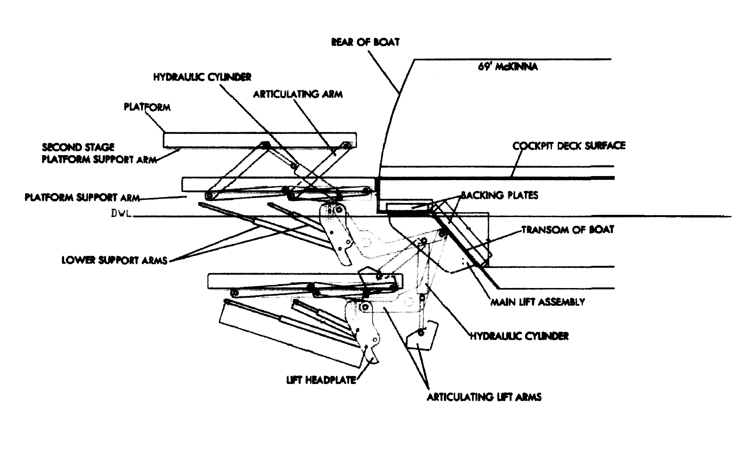
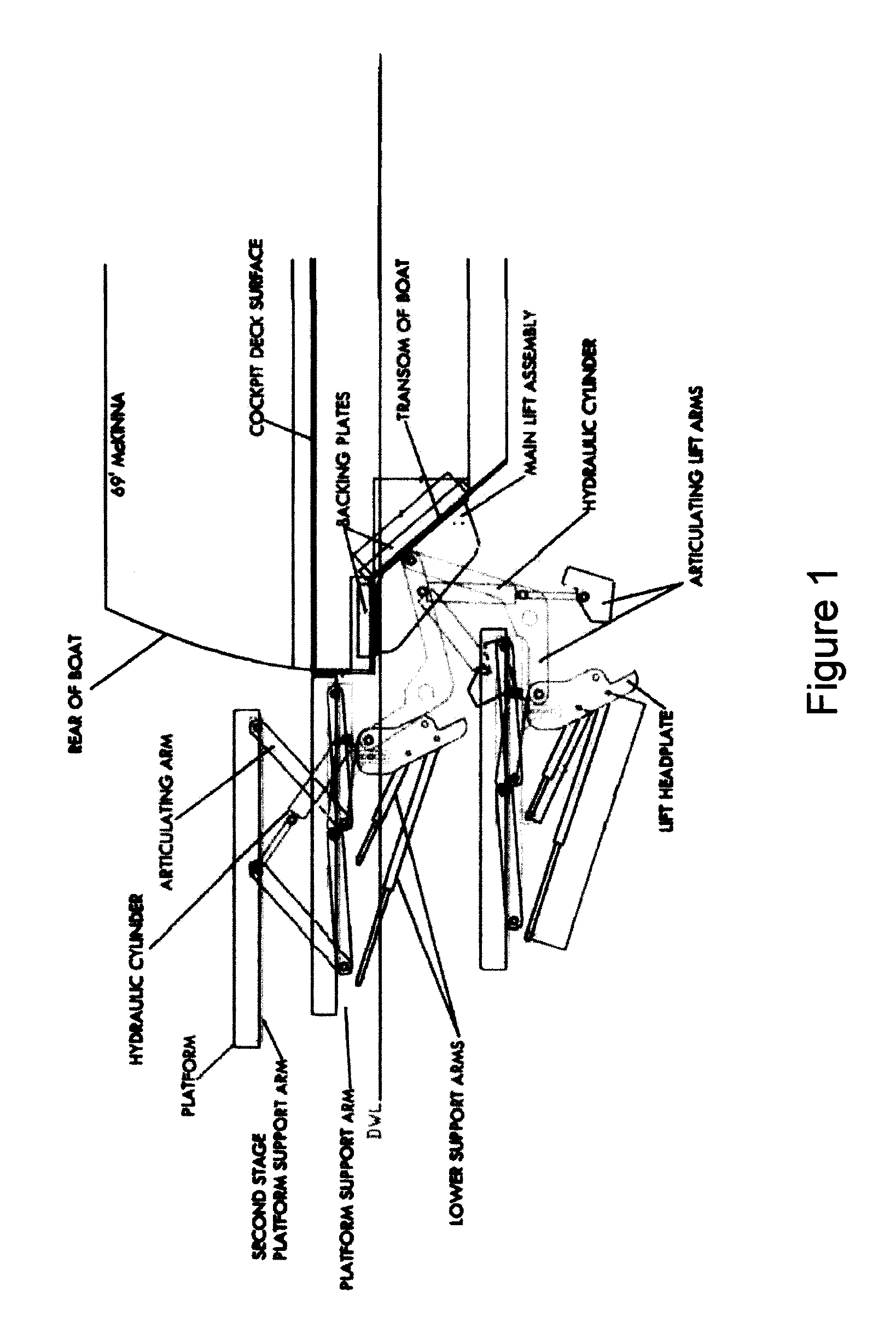
[0018]FIGS. 1 through 3 illustrate various views of the present invention two stage lift assembly for a boat swim platform. FIGS. 4 through 9 illustrate one embodiment of the present invention secured to the rear of a boat and illustrating the invention in several platform positions. FIGS. 10 and 11 illustrate isometric views of the two stage or double acting lift assembly of the present invention.

[0019]As seen in the Figures, the first stage lift assembly can be conventional, and can be a standard lift, with standard installation and standard hydraulics functionality. The present invention adds the conventional first stage lift assembly or mechanism by providing a second stage mechanism which provides a second lift mechanism for the secured platform.

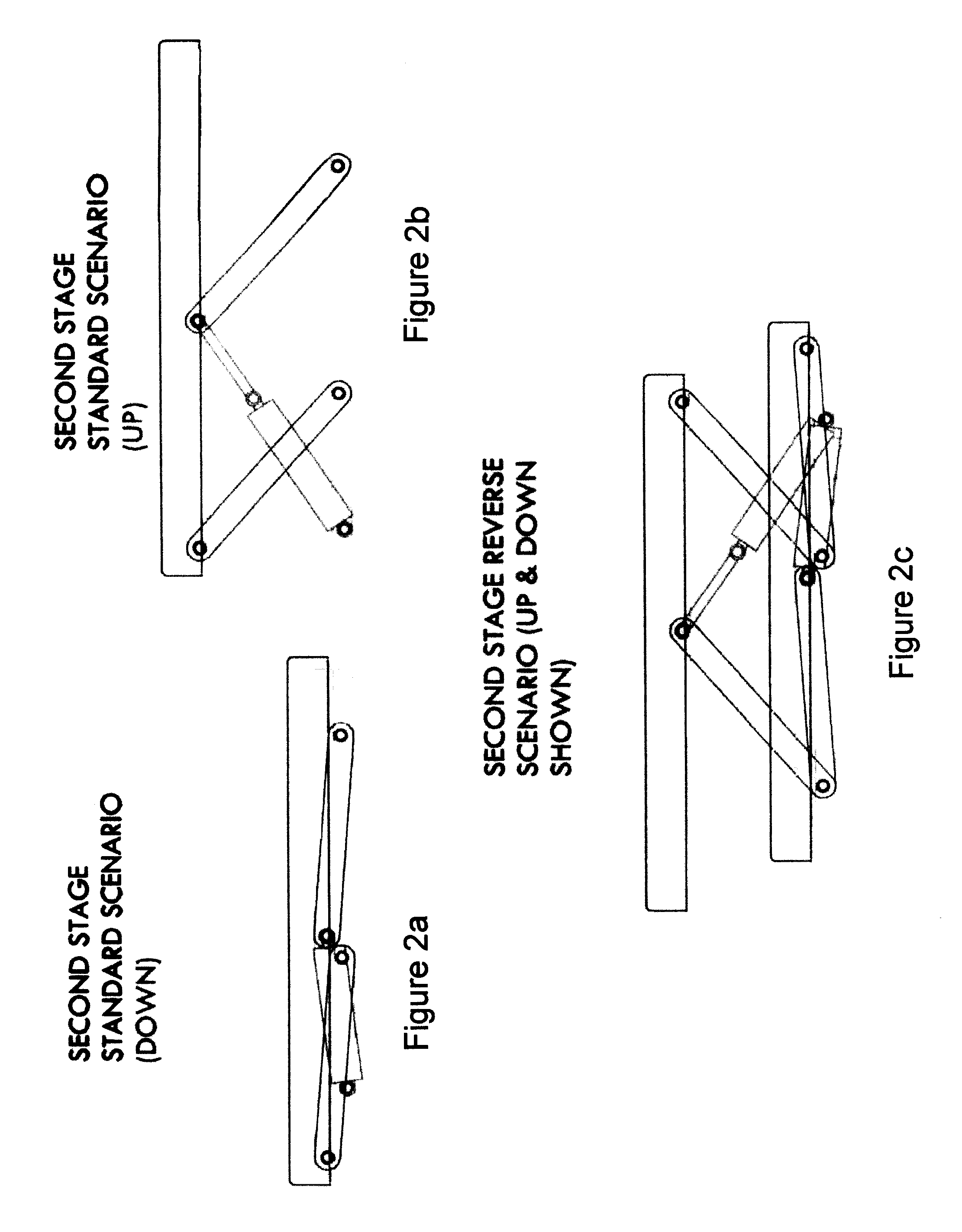
[0020]The second stage lift mechanism can be provided with two cylinders (i.e. hydraulic, etc.), though such is not considered limiting. Lower or platform support arms accommodate the cylinders and provide pivoting points. Thus, the sec...


PUM


Abstract

A second stage lift assembly for a moveable boat stern platform is disclosed and provides the ability to raise the moveable platform up an additional higher amount as compared to it's in-line level with the boat's walk-on deck or fixed platform. By being raised higher when the boat is moving, the moveable platform avoids dragging problems often encountered where the moveable platform remains at the same height as the walk-on deck or fixed platform.

Description

[0001]This application claims priority to and the benefit of U.S. Application Ser. No. 61 / 027,181, filed Feb. 8, 2008, which is incorporated by reference in its entirety.BACKGROUND OF THE INVENTION[0002]Many new boat styles include a very low deck at the boat's stern that is close to the water line. Some boats have walk-out decks and / or fixed platforms that are also close to the waterline. This deck / platform configuration is for aesthetic cosmetic or practical purposes. When installing a moveable platform at the stern of a boat, approximately 4 to 5 feet of an extension is typically realized. It is preferable that the moveable platform line up with the rear walk-out deck or fixed platform so that it acts as an extension of the boat stern. Therefore, the moveable platform is installed so that it is at the same height as the existing stern of the boat during use.[0003]One inherent problem with the moveable platform is that it typically extends beyond the stern of the boat at only 6 to...

Claims


Application Information

Patent Timeline
Patent Type & Authority Patents(United States)
IPC IPC(8): B63B17/00
CPCB63B27/16B63B27/146B63B2029/022B63B34/00
Inventor ULRICH, RICHARD
Owner TNT ELEVATOR SYST INC
Why Eureka
Try Eureka