Device for separating components of a fluid sample

a technology for fluid samples and components, applied in separation processes, centrifuges, laboratory glassware, etc., can solve the problems of clogging measuring instruments, affecting the operation of instruments, and affecting the shelf life of products, so as to avoid gel residuals and reduce separation time

Active Publication Date: 2011-05-24
BECTON DICKINSON & CO
View PDF33 Cites 34 Cited by
  • Summary
  • Abstract
  • Description
  • Claims
  • Application Information

AI Technical Summary

Benefits of technology

Preferably, the bellows includes a toroidal sealing section which, in an unbiased state of the bellows, defines an outer diameter that exceeds the inside diameter of the tube. However, the bellows can be deformed slightly so that the outer circumferential surface of the toroidal sealing section is biased against the inner circumferential surface of the tube to achieve a sealing engagement between the bellows and the tube. The bellows may be elongated by oppositely directed forces in proximity to the opposed upper and lower ends thereof. Elongation of the bellows in response to such oppositely directed forces will reduce the outside diameter of the toroidal sealing section of the bellows. Sufficient elongation of the bellows will cause the toroidal sealing section of the bellows to be spaced inwardly from the internal surface of the blood collection tube, and thereby allow the separator to move within the tube.
The ballast will cause the separator to sink into the fluid sample while the float will buoyantly remain near the surface of the fluid sample thereby causing an elongation and narrowing of the bellows. The less dense liquid phase of the fluid sample will move through the space between the separator and the walls of the tube. As noted above, the overall density of the separator is selected to be less than the density of the formed phase of the fluid sample, but greater than the density of the less dense liquid phase of the fluid sample. Thus, the separator will stabilize at a location between the formed and liquid phases of the fluid sample after a sufficient period of centrifugation. The centrifuge then is stopped. The termination of the centrifugal load enables the toroidal sealing section of the bellows to return toward its unbiased dimensions, and into sealing engagement with the interior of the tube. The less dense liquid phase of the fluid sample can be separated from the tube by either removing the closure or passing a needle through the closure. Alternatively, in certain embodiments, the more dense formed phase can be accessed through a sealed opening in the bottom end of the tube.
It is possible to obtain the high and low density regions by a variety of techniques, including molding a high density elastomeric matrix with low density components, including air bubbles or voids, distributed at an upper region therein (to provide buoyancy), or to mold a low density elastomeric matrix with high density components distributed at a lower region therein (to provide ballast). It is also possible to co-mold two or more different materials (or the same materials but having different densities) to provide the distinct densities.
The assembly of the invention is advantageous over existing separation products that use gel. For example, the separator of the invention will not interfere with analytes as compared to gels that may do so, nor will the separator of the invention interfere with therapeutic drug monitoring analytes. Other advantages that the separator may provide over gel include reduced separation time, avoidance of gel residuals, no interference with instrument probes, more acceptable blood banking tests, and a cleaner sample (where a the blood is initially provided beneath the separator) due to the fact that only the cell-free fraction contacts the upper portion of the separator.

Problems solved by technology

Moreover, the shelf-life of the product may be limited because over time globules of gel may be released from the gel mass.
These globules may enter the serum sample and thereby clog the measuring instruments.
Such clogging can lead to considerable downtime for an instrument.
In addition, no commercially available gel is completely chemically inert to all analytes.
If certain drugs are present in the blood sample when it is taken, there can be an adverse chemical reaction with the gel.

Method used


Image

  • Device for separating components of a fluid sample
  • Device for separating components of a fluid sample
  • Device for separating components of a fluid sample

Examples


Embodiment Construction

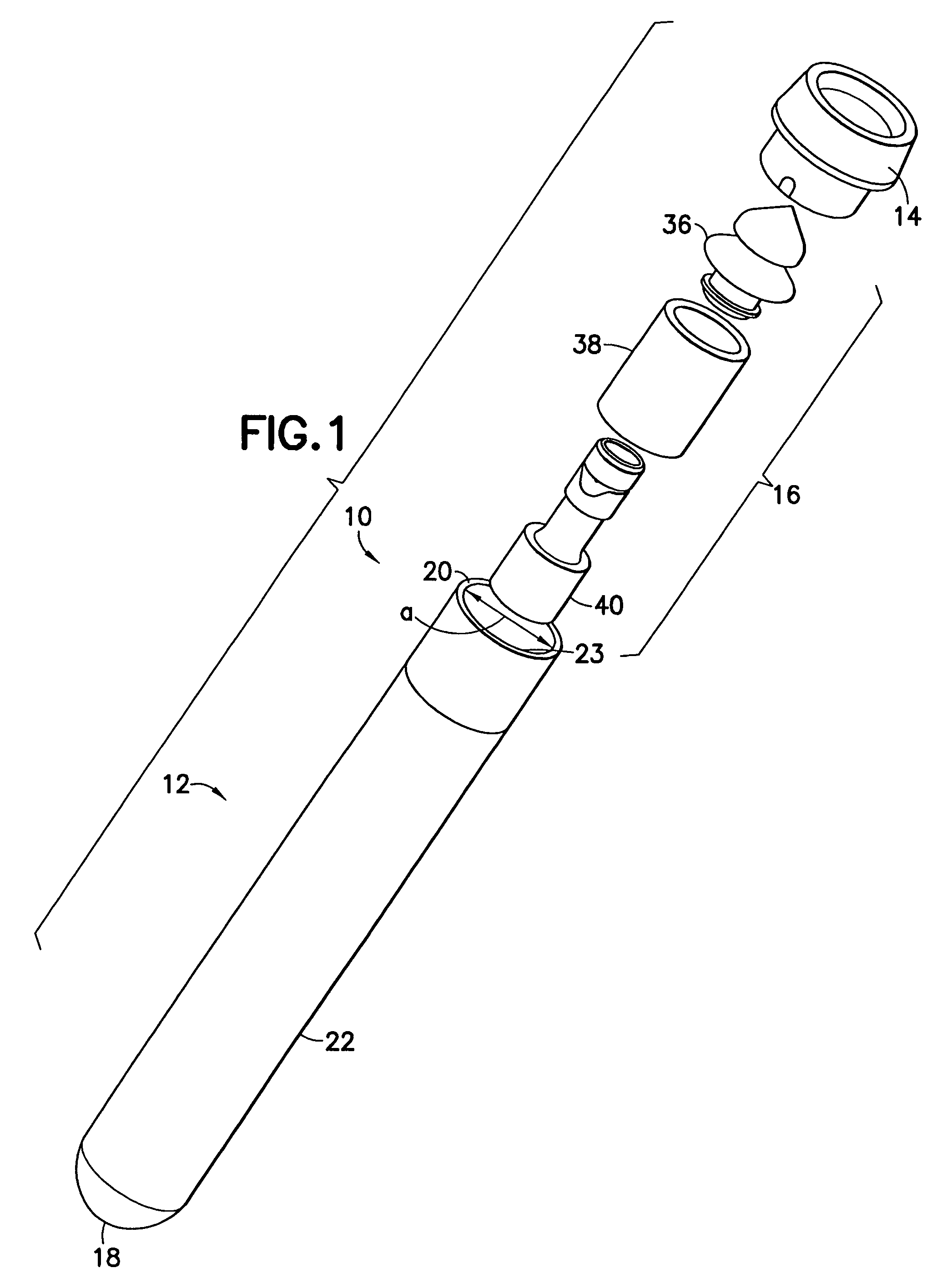
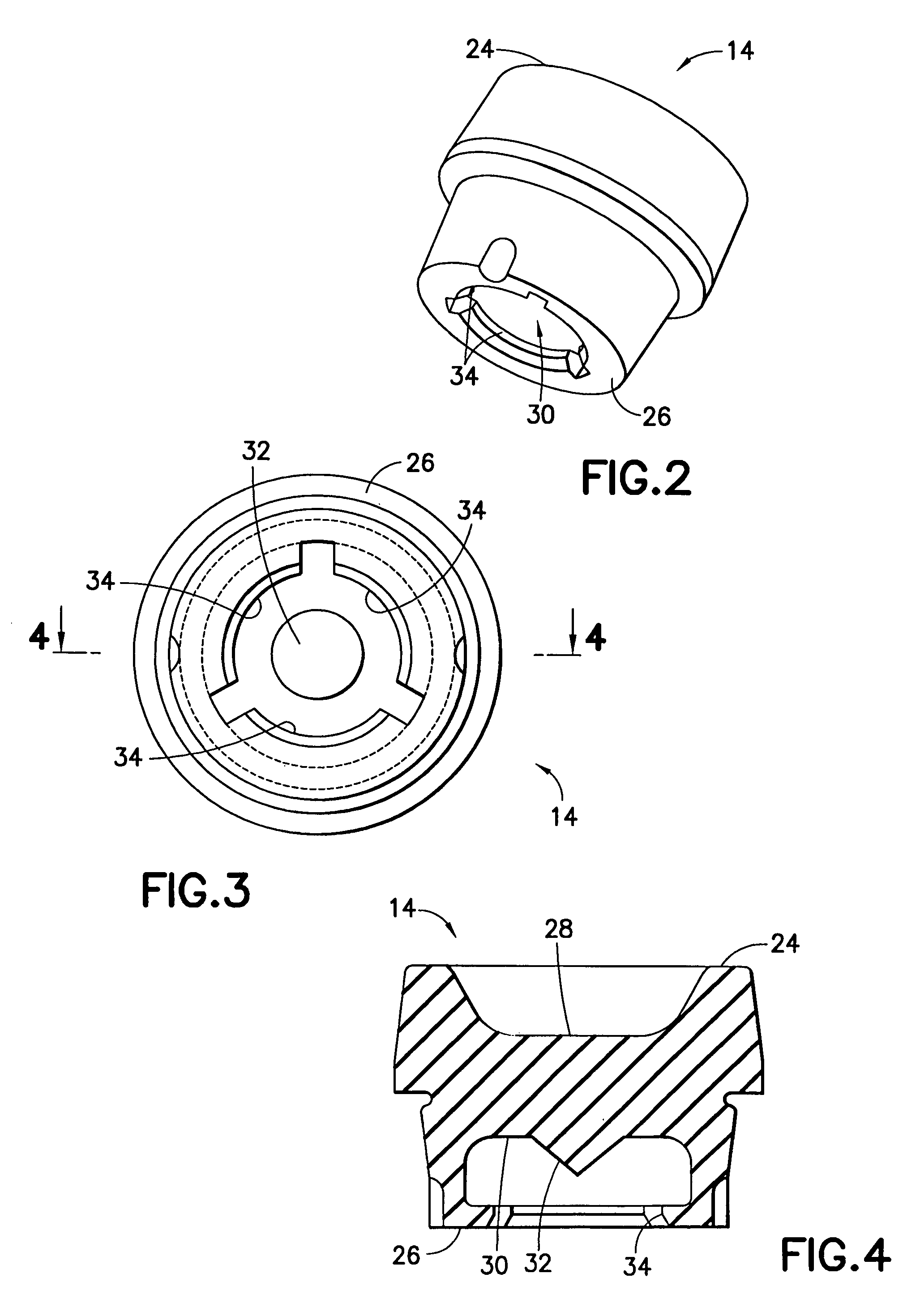
In one embodiment, the separator includes opposed top and bottom ends and comprises a bellows, a ballast and a float. The separator is disposed in the tube at a location between the top closure and the bottom of the tube. The components of the separator are dimensioned and configured to achieve an overall density for the separator that lies between the densities of the phases of a fluid sample, such as a blood sample.

The bellows of the separator is molded from a resiliently deformable material that exhibits good sealing characteristics when placed against an adjacent surface. The bellows has an upper end that is at or in proximity to the top end of the separator and an opposed lower end that is disposed between the opposed ends of the separator.

The upper end of the bellows may be formed from a material that may be pierced by a needle cannula for depositing a fluid sample into the tube. Additionally, the upper end of the bellows initially may be engaged releasably with the closure mo...


PUM

PropertyMeasurementUnit
densitiesaaaaaaaaaa
densityaaaaaaaaaa
rotationaaaaaaaaaa

Abstract

A device for separating heavier and lighter fractions of a fluid sample is provided, the device including a container and a unitary separator located therein, the separator having an overall density between the heavier and light fractions. The separator is capable of moving between the fractions upon centrifugation, and sealing the fractions from one another when centrifugation ends.

Description

BACKGROUND OF THE INVENTION1. Field of the InventionThis invention relates to a device for separating heavier and lighter fractions of a fluid sample, in particular a container containing a separator that provides such separation of blood upon centrifugation.2. Description of Related ArtDiagnostic tests may require separation of a patient's whole blood sample into components such as serum or plasma (a lighter phase component) and red blood cells (a heavier phase component). Samples of whole blood are typically collected by venipuncture through a cannula or needle attached to a syringe or an evacuated collection tube. Separation of the blood into serum or plasma and red blood cells is then accomplished by rotation of the syringe or tube in a centrifuge. The tube or syringe generally contains a barrier that moves between the two phases upon centrifugation, and maintains that separation thereafter to allow subsequent examination of the individual components.A variety of devices have be...

Claims


Application Information

Patent Timeline
Patent Type & Authority Patents(United States)
IPC IPC(8): B01D21/00B01D45/00B01L3/14G01N33/49
CPCB01L3/50215B04B7/08G01N33/491Y10T29/49826
Inventor LOSADA, ROBERT J.LIN, FU-CHUNGLUSARDI, GREGORY L.
Owner BECTON DICKINSON & CO
Why Eureka
Try Eureka