Shifting device for shifting a motor vehicle gear box

a technology for shifting devices and motor vehicles, applied in the direction of machines/engines, mechanical equipment, positive displacement engines, etc., can solve the problems of short shift time and small moving mass

Inactive Publication Date: 2011-05-31
ZF FRIEDRICHSHAFEN AG
View PDF15 Cites 7 Cited by
  • Summary
  • Abstract
  • Description
  • Claims
  • Application Information

AI Technical Summary

Benefits of technology

[0011]The invention is based on recognition of the fact that the stated objective can be achieved with a 2-way shift cylinder of simple construction, which is connected to the shift element, in particular a shift fork or a shift rocker, in a detachable manner.
[0013]This arrangement provides a shifting device which is simple to construct, has compact overall dimensions and is also simple to assemble and to maintain. Thus, to assemble the shifting device, it is only necessary to fit a shift rocker in the shift cylinder and correspondingly to remove it again when dismantling. Since the cylinder or cylinder piston is connected directly to the shift fork or shift rocker, the shift travel paths are very short and this leads to small moving masses and, along with very short line lengths for the fluid, to very short shift times.

Problems solved by technology

Since the cylinder or cylinder piston is connected directly to the shift fork or shift rocker, the shift travel paths are very short and this leads to small moving masses and, along with very short line lengths for the fluid, to very short shift times.

Method used


Image

  • Shifting device for shifting a motor vehicle gear box
  • Shifting device for shifting a motor vehicle gear box
  • Shifting device for shifting a motor vehicle gear box

Examples


first embodiment

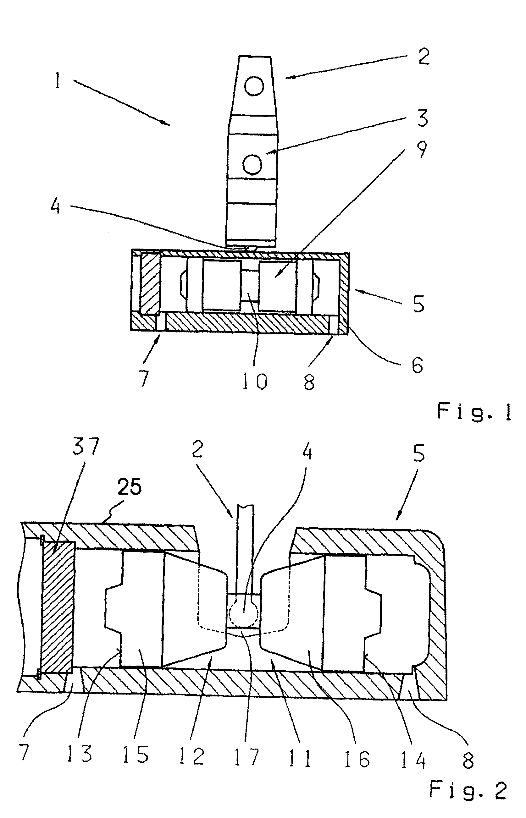
[0028]The shift cylinder 5 of the first embodiment, shown in FIGS. 1 and 2, is made as a horizontally acting, shift cylinder 11 that can be actuated from both sides which, as can be seen in FIG. 2, comprises a dual piston 12 whose piston faces 13, 14 can be acted upon by the fluid passed into the cylinder housing 6 through the pressure lines 7, 8. The dual piston 12 consists of two component pistons 15 and 16 connected to one another by a piston rod 17. The piston rod 17 is also connected in a detachable manner to the free end 4 of the shift element 2.

[0029]If fluid flows through line 7 and acts to exert pressure on the piston face 13 of the piston 15, the dual piston 12 is displaced to the right and the free end 4 of the shift element 2 as well is moved to the right. Depending on the mounting of the shift element 2, this will then undergo a lateral displacement or a tilting movement and, by virtue of known action upon coupling links, will bring about a corresponding shift operation...

second embodiment

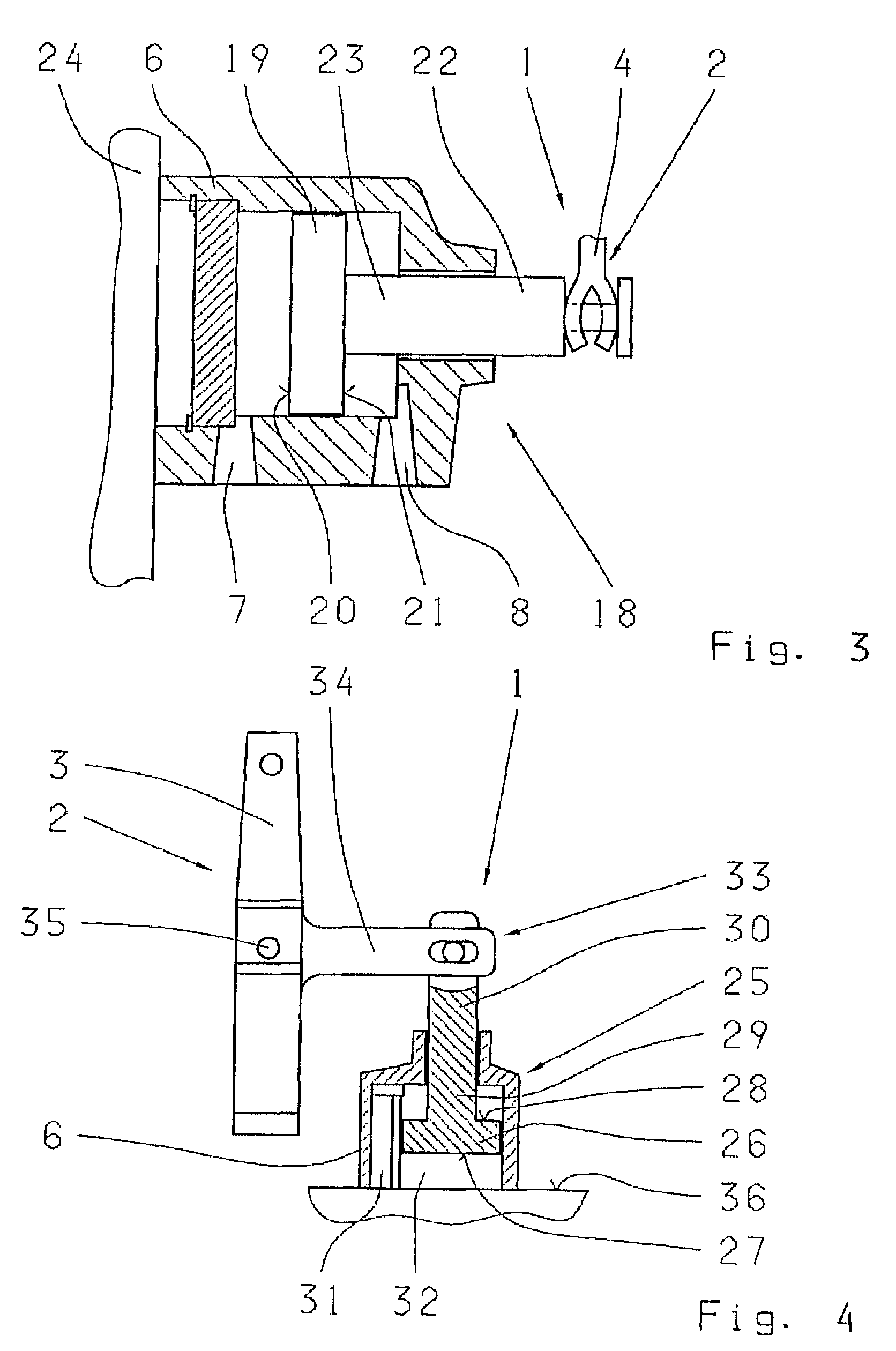
[0030]FIG. 3 shows shifting device 1 represented in longitudinal section. This shifting device 1 corresponds in principle to the shifting device 1 shown in FIG. 1, but the shift cylinder 5 is now made as a horizontally acting, stepped shift cylinder 18 that can be actuated from both sides. In contrast to the shift cylinder 11 in FIGS. 1 and 2, the shift cylinder 18 has only one piston 19, whose piston faces 20, 21 can be acted upon by the fluid and whose piston rod end 22 of a piston rod 23, located outside the cylinder housing 6, is connected to the free end 4 of the shift element 2.

[0031]The cylinder housing 6 of the shift cylinder 18 is, in addition, connected to a transmission housing wall 24 or to the housing of a hydraulic shift mechanism.

third embodiment

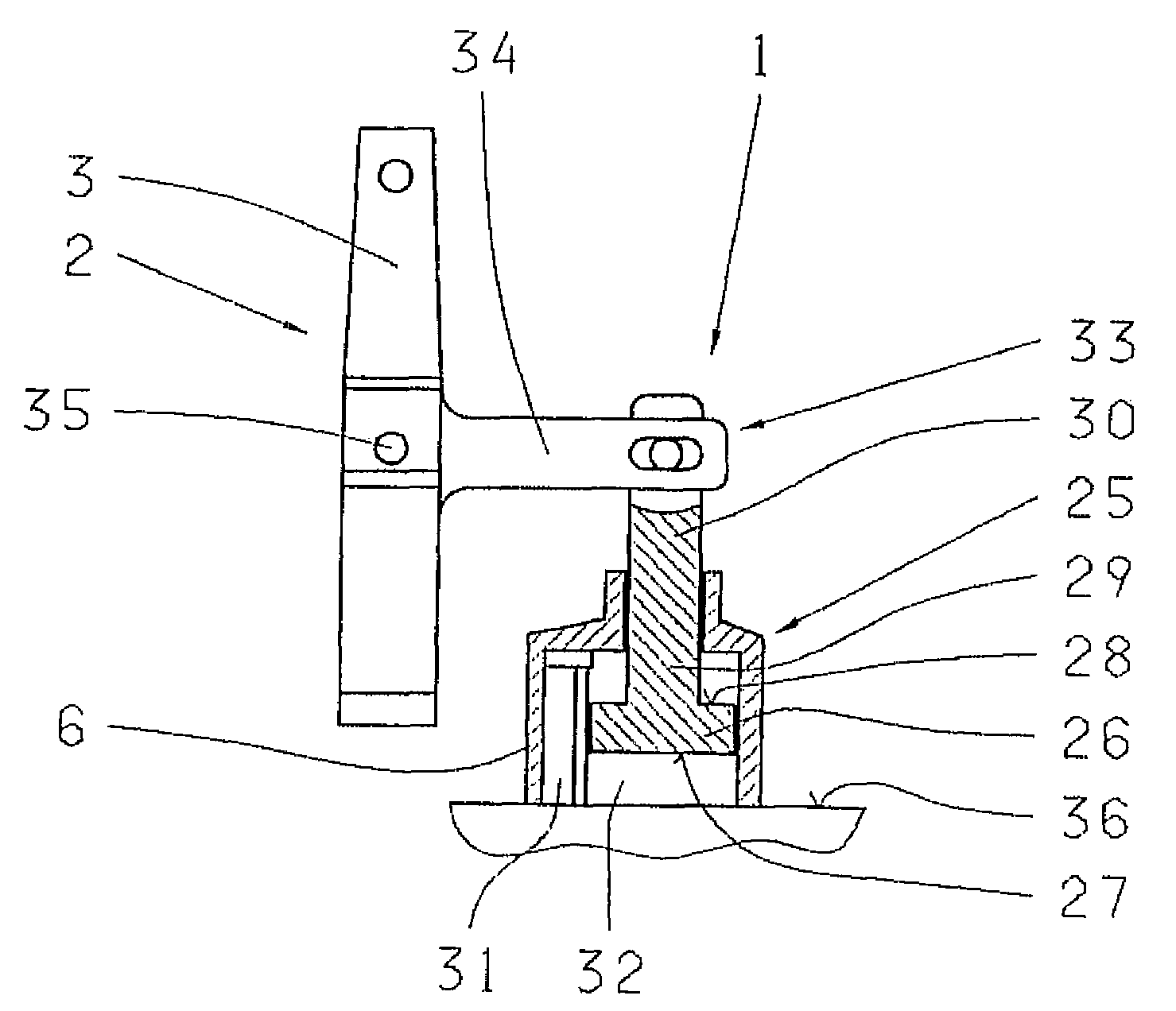
[0032]FIG. 4 shows the shift element 1 in which the shift cylinder 5 is this time made as a vertically acting, stepped shift cylinder 25 that can be actuated from both sides and which corresponds largely to the shift cylinder 18 shown in FIG. 2. Accordingly, the shift cylinder 25 has a piston 26 with two faces 27 and 28 and with a piston rod 29, whose piston rod end 30, located outside the cylinder housing 6, is connected to the free end 4 of the shift element 2. In contrast to the example embodiment shown in FIG. 2, the shift cylinder 25 has vertical pressure lines 31 and 32 through which fluid can flow into the shift cylinder 25 and act to exert pressure on the faces 27 and 28. The orientation of the cylinder housing 6, the piston rod 29 and the piston rod end 30 is also vertical.

[0033]The shift element 2, shown in FIG. 4 in the form of a shift rocker 3 has a free end 33 in the form of a web 34 extending at a right-angle from the shift rocker 3. The free end is connected to the pi...


PUM


Abstract

A shifting device (1) for shifting a motor vehicle transmission with a shift selector shaft on which a plurality of shift elements (2) such as shift forks or shift rockers (3) are arranged and can be displaced to carry out a shifting operation. The shifting device (1) includes one hydraulic shift cylinder (5, 11, 18, 25), that can be actuated from both sides, with a piston (9, 15, 16, 19, 26) that can be displaced within a cylinder housing (6) and which is actively connected with a shift element (2) to be actuated. To simplify a shifting device (1) of this type, the piston (9, 15, 16, 19, 26) has a piston rod (10, 17, 23, 29) that follows the movement of the piston (9, 15, 16, 19, 26) and can be connected directly to the shift element (2) in a detachable manner.

Description

[0001]This application is a national stage completion of PCT / EP2007 / 051032 filed Feb. 2, 2007, which claims priority from German Application Serial No. 10 2006 006 868.8 filed Feb. 15, 2006.FIELD OF THE INVENTION[0002]The invention concerns a shifting device for shifting a motor vehicle transmission.BACKGROUND OF THE INVENTION[0003]To shift a transmission, a shifting device is provided inside the transmission in a vehicle to help engage and disengage individual gears. For this purpose, components of the shifting device can be actuated manually by the driver of the vehicle or shift elements or actuators that can be operated by auxiliary means, for example hydraulic fluid, are provided and these act upon the components of the shifting device, as necessary, to shift the gears.[0004]From EP 0 541 035 B1, a shifting device for multiple-gear, range-change transmissions is known, which comprises valves and shift cylinders in which there are pistons actuated by a control fluid. Shift rods a...

Claims


Application Information

Patent Timeline
Patent Type & Authority Patents(United States)
IPC IPC(8): F01B9/00
CPCF16H63/3023F16H61/30F16H2063/325
Inventor KAUFFELDT, RUDOLFMARTIN, HANS-JOACHIMGUMPOLTSBERGER, GERHARDEBENHOCH, MICHAELRIEGER, WOLFGANGDRABEK, MICHAELCSAJAGI, STEFAN
Owner ZF FRIEDRICHSHAFEN AG
Why Eureka
Try Eureka