Secured plug connection and method for its production

a secure plug and connection technology, applied in the field of plug connection, can solve problems such as damage to electrical contacts, and achieve the effect of small toleran

Inactive Publication Date: 2011-05-31
KNORR-BREMSE SYST FUER NUTZFAHRZEUGE GMBH
View PDF16 Cites 14 Cited by
  • Summary
  • Abstract
  • Description
  • Claims
  • Application Information

AI Technical Summary

Benefits of technology

[0007]The exemplary embodiments and / or exemplary methods of the present invention is based on the concept that a separate plug connection securing arrangement is provided which is independent of the connection arrangement of the components and secures the plug connection against movements of the plug relative to the socket and vice versa. Neither the plug nor the socket can then carry out relative movements with respect to one another which damage the electrical contacts. The decisive factor in this arrangement is that the connection or the securing of the connection between plug and socket is independent of the connection between the two electrical or electronic components and is established separately from the latter.
[0008]To establish the secured plug connection according to the present invention, the housings of the two components, for example a control device and an actuator / sensor assembly of a braking device of a utility vehicle are first positioned in assembly position with respect to one another. By correspondingly arranging the plug and the socket at the respective housing, the plug and the socket can already be positioned with respect to one another in this assembly position in such a manner that when the housings of the components are joined, the plug is also at least aligned with the socket. As well, the plug connection, i.e. an electrical contact between plug and socket, can already be established at least partially in this manner. The plug connection securing arrangement is then used for completing or securing the plug connection, for example in the form of a screw connection which is tightened. The plug is fixed in position with respect to the socket by the firm screwing so that no further relative movements which negatively influence the contact retention capability can take place.
[0010]So that the plug connection is produced at least partially simultaneously with the joining of the housings of the components, relatively small tolerances must be maintained in the positioning of the plug with respect to the housing of the one component or the socket relative to the housing of the other component which is associated with a certain cost expenditure. By comparison, it may be advantageous if the plug on the one component and / or the socket on the other component is held via an elastic body in such a manner that the latter is deformable due to forces which occur during the production and / or in the securing of the plug connection by the plug connection securing arrangement. The elastic body is then used for compensating for tolerance in the production or securing of the plug connection since, for example, the plug and / or the socket, as a condition of the elasticity, can be brought out of their initial position in a plane perpendicularly to the plug-in direction in such a manner that the plug is aligned with the socket and the plug connection can thus be produced at all.
[0011]As an alternative or additionally, the plug and the socket can already be aligned with one another or then already partially engage one another, for example, already in the assembly position of the components, the distance of the plug from the socket being too large or too small due to tolerances in the plug-in direction. The elastic body can then provide for a compensation in parallel with the plug-in direction by elastically deforming during the tightening of the screw connection in order to ensure that the plug achieves its full insertion depth in the socket.
[0012]In this arrangement, the elastic body can contain a circuit board which is flexible perpendicularly to the board plane, a lead frame which is flexible perpendicularly to the frame plane or a cable tree which is arranged inside one of the components. In this manner, an advantageous dual function is achieved since the circuit board or the lead frame, apart from its function as carrier of electrical and / or electronic components, simultaneously takes over the function of the elastic holder for the plug or the socket.
[0013]The plug connection securing arrangement may contain at least one screw connection which is screwed with its screw shank through a thread of the elastically supported socket or of the elastically supported plug and can be screwed into at least one threaded hole of one of the components in such a manner that the elastically supported plug or the elastically supported socket, when the screw is screwed into the threaded hole of the one component, is screwed in the direction of the socket rigidly supported at the other component or of the plug rigidly supported at the other component. The screw thus forms not only a securing arrangement of the connection between the plug and the socket but, when the screw connection is tightened, it simultaneously ensures that the plug elastically supported at the one component or the socket elastically supported at the one component is transported in the direction of the socket rigidly supported at the other component or of the plug rigidly supported at the other component in the sense of a linear guidance.
[0014]In this arrangement, the screw can be locked with its screw head against the plug rigidly supported at the one component or against the socket rigidly supported at the one component and conducted with its screw shank through a hole in the rigidly supported socket or in the rigidly supported plug.
[0011]As an alternative or additionally, the plug and the socket can already be aligned with one another or then already partially engage one another, for example, already in the assembly position of the components, the distance of the plug from the socket being too large or too small due to tolerances in the plug-in direction. The elastic body can then provide for a compensation in parallel with the plug-in direction by elastically deforming during the tightening of the screw connection in order to ensure that the plug achieves its full insertion depth in the socket.

Problems solved by technology

Neither the plug nor the socket can then carry out relative movements with respect to one another which damage the electrical contacts.

Method used


Image

  • Secured plug connection and method for its production
  • Secured plug connection and method for its production

Examples


Embodiment Construction

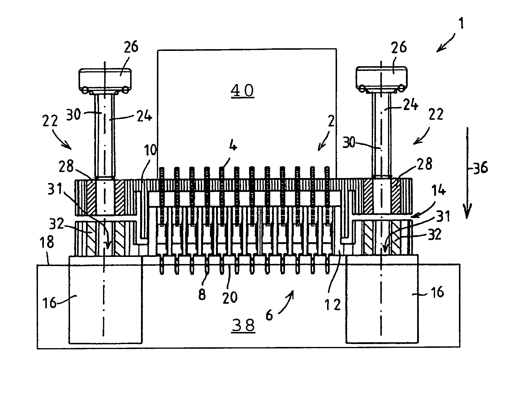
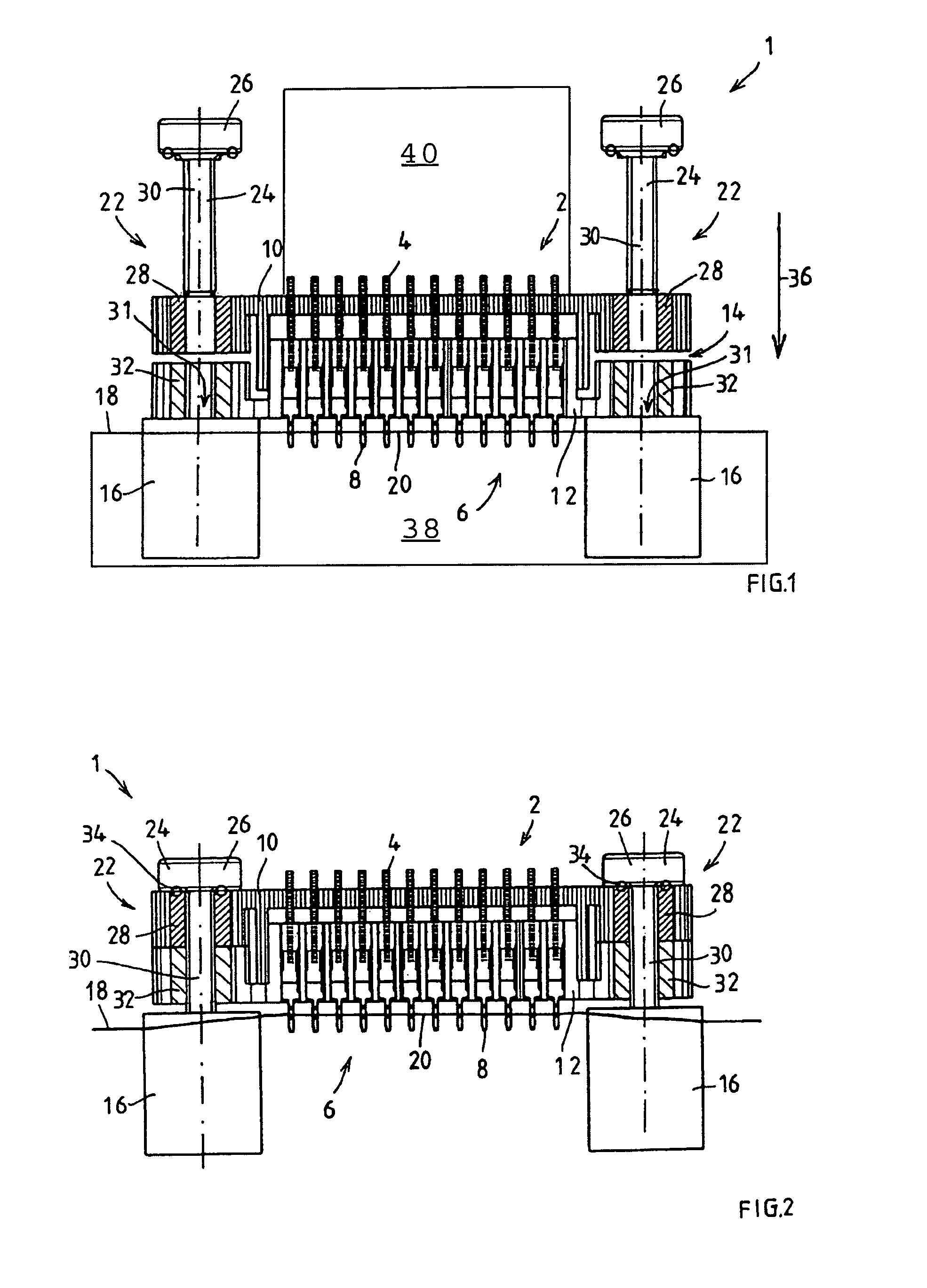
[0019]FIG. 1 shows a plug connection 1 between electrical and / or electronic components according to an exemplary embodiment of the present invention in which it is arranged between an actuator and sensor assembly 38, not shown here to scale, and a control device 40 allocated to this assembly, also not shown here to scale, of a braking device of a vehicle, particularly of a utility vehicle. In this arrangement, for example, a plug 2 of the plug connection 1 with flat contacts 4 is attached to the control device and a socket 6 of the plug connection 1 with ferrules 8 accommodating the flat contacts 4 is attached to the actuator and sensor assembly. Naturally, the allocation can also be reversed.

[0020]Together with the actuator and sensor assembly, the control device forms, for example, a pressure control module (DRM) as component of an electronic / pneumatic system, particularly a braking system, and the interface between the electronic part and the pneumatic part. The pressure control ...


PUM


Abstract

A plug connection between electrical and / or electronic components, in which electrical plug contacts of a plug which is arranged directly adjacently to one component are inserted into a socket which is arranged directly adjacently to the other component, with the components being interlocked with one another by a connection arrangement or being combined to form an assembly, and in which a separate plug connection securing arrangement which is independent of the connection arrangement of the components is provided to secure the plug connection against movements of the plug relative to the socket and vice versa.

Description

FIELD OF THE INVENTION[0001]The present invention relates to a plug connection between electrical and / or electronic components, in which electrical plug contacts of a plug which is arranged directly adjacently to one component are inserted into a socket which is arranged directly adjacently to the other component, with the components being interlocked with one another by a connection arrangement or being combined to form an assembly. Furthermore, a method for producing such a plug connection is also described herein.BACKGROUND INFORMATION[0002]In many applications, the control electronics for driving actuator / sensor assemblies in brake assemblies of utility vehicles are accommodated in a separate module in order to enable them to be used in different models. To electrically connect an actuator / sensor assembly to the associated control electronics, a central plug connection must be used for the signal / current transmission to the actuator / sensor assembly. In this arrangement, the cont...

Claims


Application Information

Patent Timeline
Patent Type & Authority Patents(United States)
IPC IPC(8): H01R13/64
CPCH01R13/6315H01R13/6215
Inventor KLINGER, HERBERTBEHRENDT, NORBERTTHOMAS, GERHARD
Owner KNORR-BREMSE SYST FUER NUTZFAHRZEUGE GMBH
Why Eureka
Try Eureka