Turbojet having an electricity generator arranged in its fan

a technology of turbine jets and turbine engines, which is applied in the direction of electric generator control, engine starters, instruments, etc., can solve the problems of little or no disturbance in installation and maintenance of electricity generators, and achieve the effect of reducing the number of turbines

Active Publication Date: 2011-05-31
SN DETUDE & DE CONSTR DE MOTEURS DAVIATION S N E C M A
View PDF25 Cites 41 Cited by
  • Summary
  • Abstract
  • Description
  • Claims
  • Application Information

AI Technical Summary

Benefits of technology

[0019]The arrangement of the electricity generator in the fan, i.e. more precisely on moving portions of the fan and on stationary portions such as the fan casing, presents several advantages.
[0021]Furthermore, the fan is a cold zone, thereby avoiding problems that might be caused by high temperatures. Thus, in the electricity generator of the invention, the magnets are not cooled, since the temperature within the fan never reaches the Curie temperature above which they would lose their magnetic properties.
[0025]Finally, as mentioned above, it is better to take power from the low pressure spool rather than from the high pressure spool. By arranging the electricity generator in the fan, this condition is satisfied and better efficiency is thus obtained, with better conversion of mechanical power into electrical power, and above all, avoiding the problems of turbojet operability and instability at low speeds that arise when too much power is taken from the high pressure spool.
[0027]The presence of such a second electricity generator in addition to the electricity generator located in the fan enables power to be taken by the two electricity generators in shared manner, thereby further enhancing engine operability, in particular at low speeds.

Problems solved by technology

Installation and maintenance of the electricity generator are therefore disturbed little or not at all by problems of available space.

Method used


Image

  • Turbojet having an electricity generator arranged in its fan
  • Turbojet having an electricity generator arranged in its fan
  • Turbojet having an electricity generator arranged in its fan

Examples


Embodiment Construction

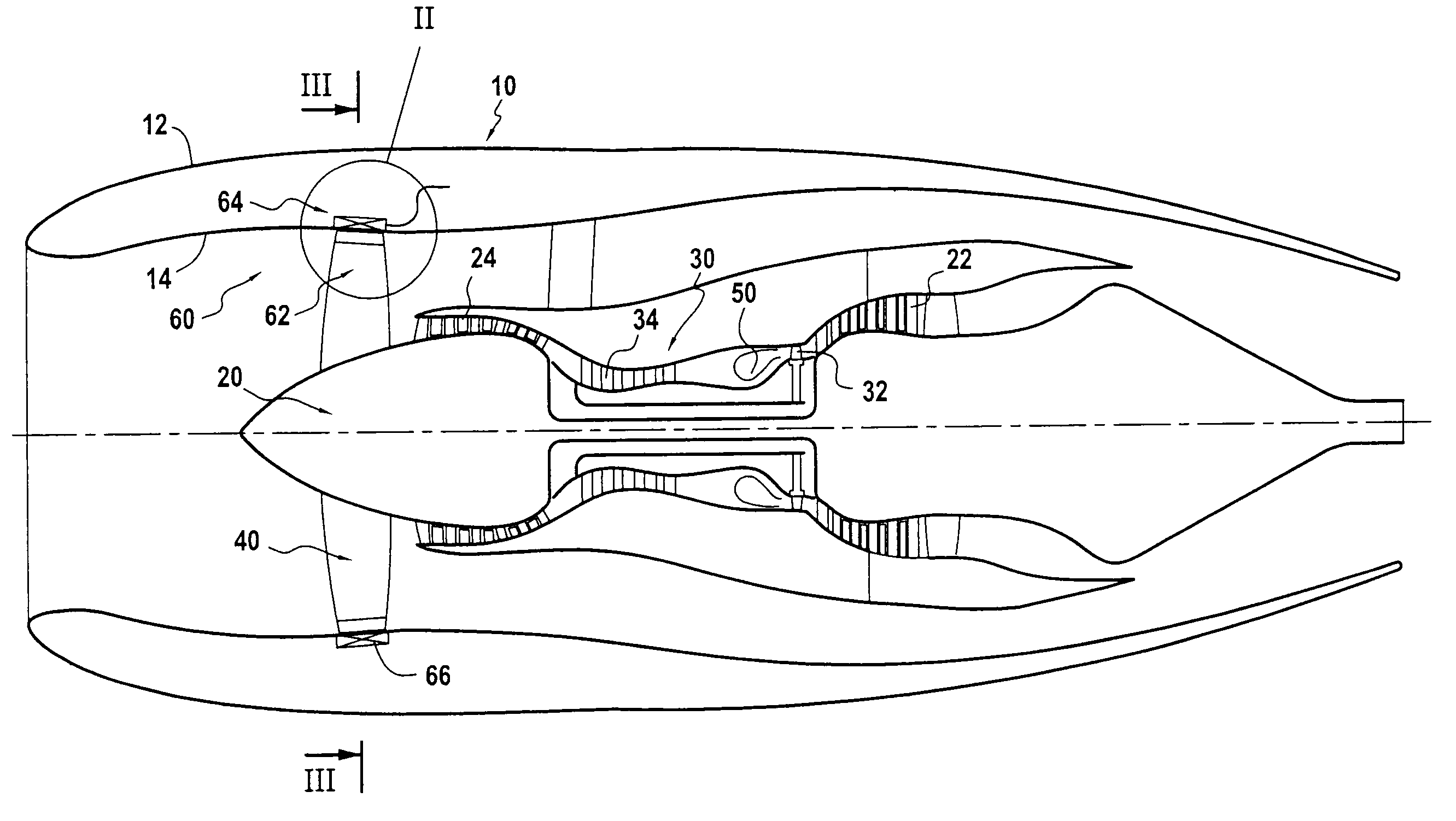
[0034]The turbojet 10 shown in the figures is of the conventional two-spool type, having a high pressure spool 30 with a high pressure compressor 34 and a high pressure turbine 32, and a low pressure spool 20 with a low pressure compressor 24 and a low pressure turbine 22. The low pressure spool 20 drives a fan 40 disposed in a fan casing 14. The fan casing 14 itself forms part of the engine nacelle 12 of the turbojet 10.

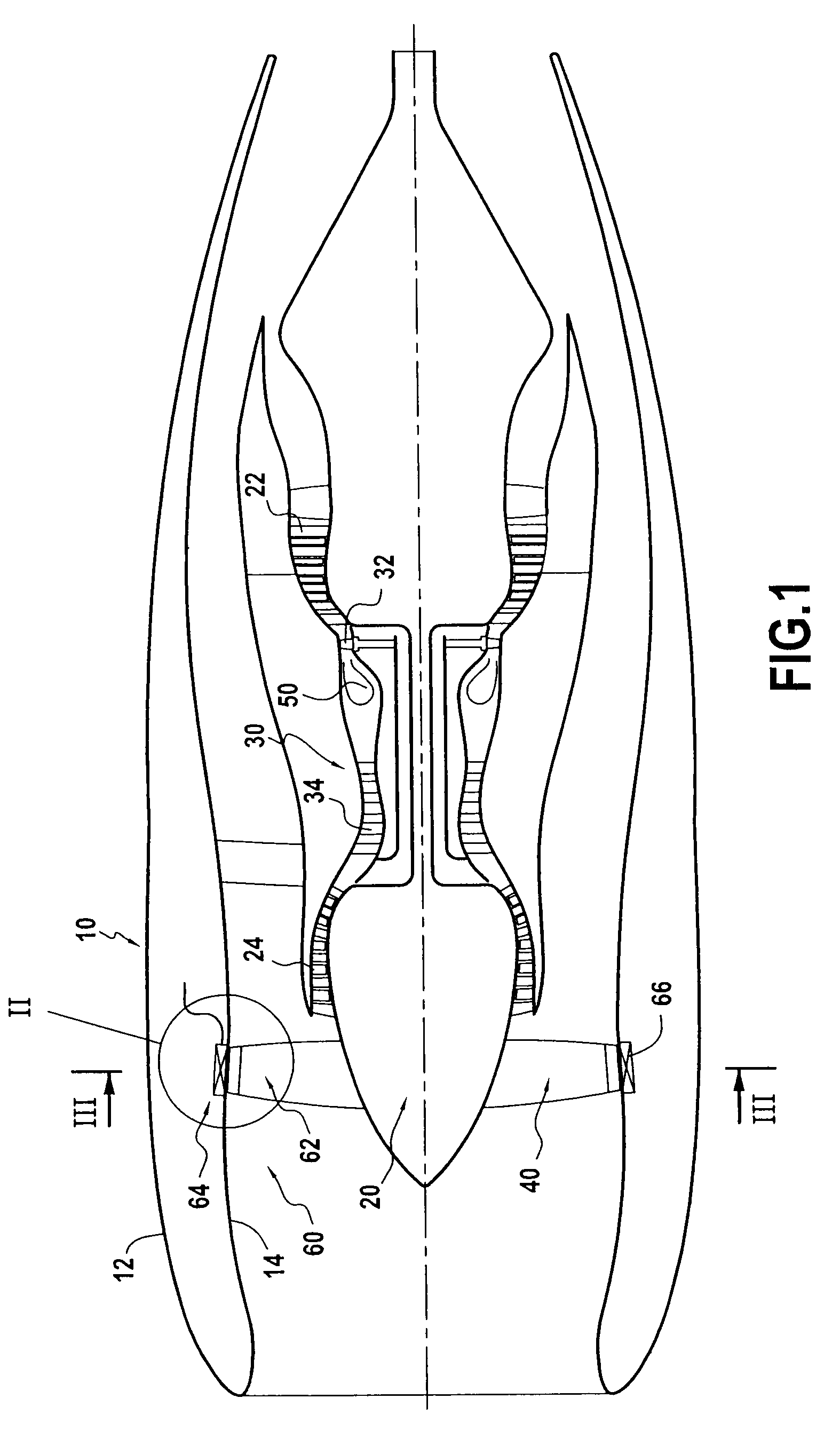
[0035]A preferred embodiment of the invention is described below with reference to FIG. 2. This figure shows the region of the turbojet in which the electricity generator 60 of the invention is arranged, i.e. the fan region.

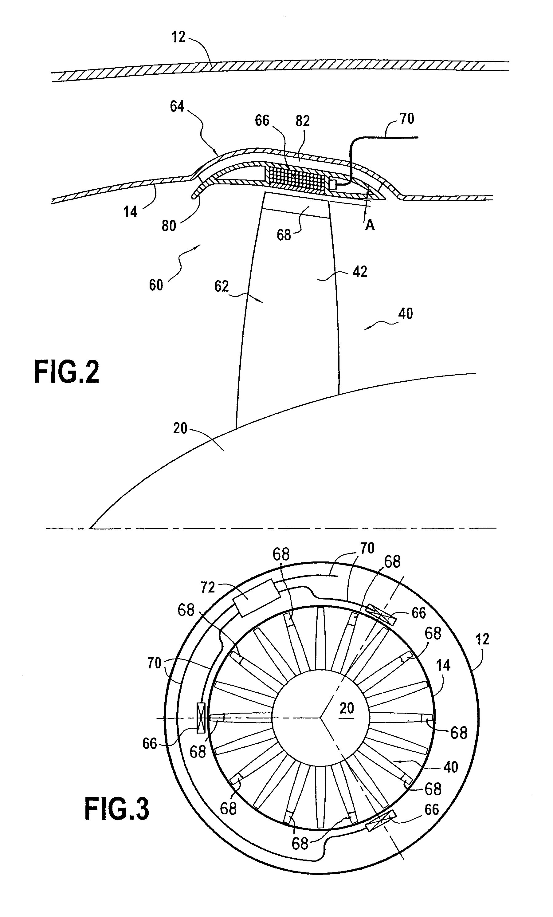
[0036]The electricity generator 60 is located at the periphery of the fan and comprises a rotor 62 incorporated with the radially outer ends of the fan blades, and a stator 64 incorporated in the fan casing.

[0037]The rotor 62 includes permanent magnets 68 fastened to the ends of the fan blades 42 so as to create a rotating field; it is thus locat...


PUM


Abstract

The turbojet comprises a high pressure spool and a low pressure spool driving a fan. In order to produce electricity, it further includes an electricity generator arranged in the fan and taking power therefrom. The generator comprises a rotor incorporated in the fan and a stator incorporated in the fan casing. This disposition for the electricity generator avoids problems of engine operability at low speed and enables mechanical power to be converted into electrical power with high efficiency. In addition, installation and maintenance of the electricity generator are facilitated by the generator being implanted in the fan.

Description

FIELD OF THE INVENTION[0001]The invention relates to a two-spool turbojet comprising a high pressure spool and a low pressure spool; the invention relates more particularly to an improvement enabling mechanical power to be taken off so as to provide electricity to the remainder of the airplane.BACKGROUND OF THE INVENTION[0002]Conventionally, a two-spool turbojet comprises an engine nacelle housing a high pressure spool comprising a high pressure compressor and a high pressure turbine, and a low pressure spool comprising a low pressure compressor and a low pressure turbine and driving the fan.[0003]The function of such a turbojet is generally not only to provide the airplane with thrust, but also to provide the airplane with electricity for various purposes such as powering computers, cabin lighting, etc.[0004]The present trend is to increase the amount of mechanical power that is taken off and converted into electrical power, given the increasing role played by electrical means, whi...

Claims


Application Information

Patent Timeline
Patent Type & Authority Patents(United States)
IPC IPC(8): H02K55/00F02K5/02
CPCF01D15/10F02K3/06H02K7/1823H02K21/14F05D2220/764F05D2220/76F05D2220/766F05D2220/768
Inventor COLIN, ANTOINE
Owner SN DETUDE & DE CONSTR DE MOTEURS DAVIATION S N E C M A
Why Eureka
Try Eureka