Lens array

a technology of arrays and lenses, applied in the field of arrays, can solve the problems of non-uniformity of the characteristics of the lens elements, the difference in the supply amount between the cells, etc., and achieve the effect of uniformizing the characteristics of the lens

Inactive Publication Date: 2011-05-31
SONY CORP
View PDF11 Cites 35 Cited by
  • Summary
  • Abstract
  • Description
  • Claims
  • Application Information

AI Technical Summary

Benefits of technology

[0019]According to the present invention, instead of the structure in which the periphery of each lens element is completely covered, the structure is adopted in which the adjacent lens elements liquidly communicate with each other. Therefore, differences in the amounts of the first liquid and the second liquid between the lens elements can be avoided and the lens characteristics can be made uniform.
[0023]As described above, in the lens array according to the present invention, the lens elements liquidly communicate with each other. Therefore, differences in the amounts of the first liquid and the second liquid between the lens elements can be avoided and the lens characteristics can be made uniform. In addition, a structure having a very small dimension, which cannot be obtained by a liquid introducing method using a syringe, a dispenser nozzle, or the like, can be easily obtained.

Problems solved by technology

In addition, there may be a case where the supply amount differs between the cells and characteristics of the lens elements 53 become non-uniform.

Method used


Image

  • Lens array
  • Lens array
  • Lens array

Examples


first embodiment

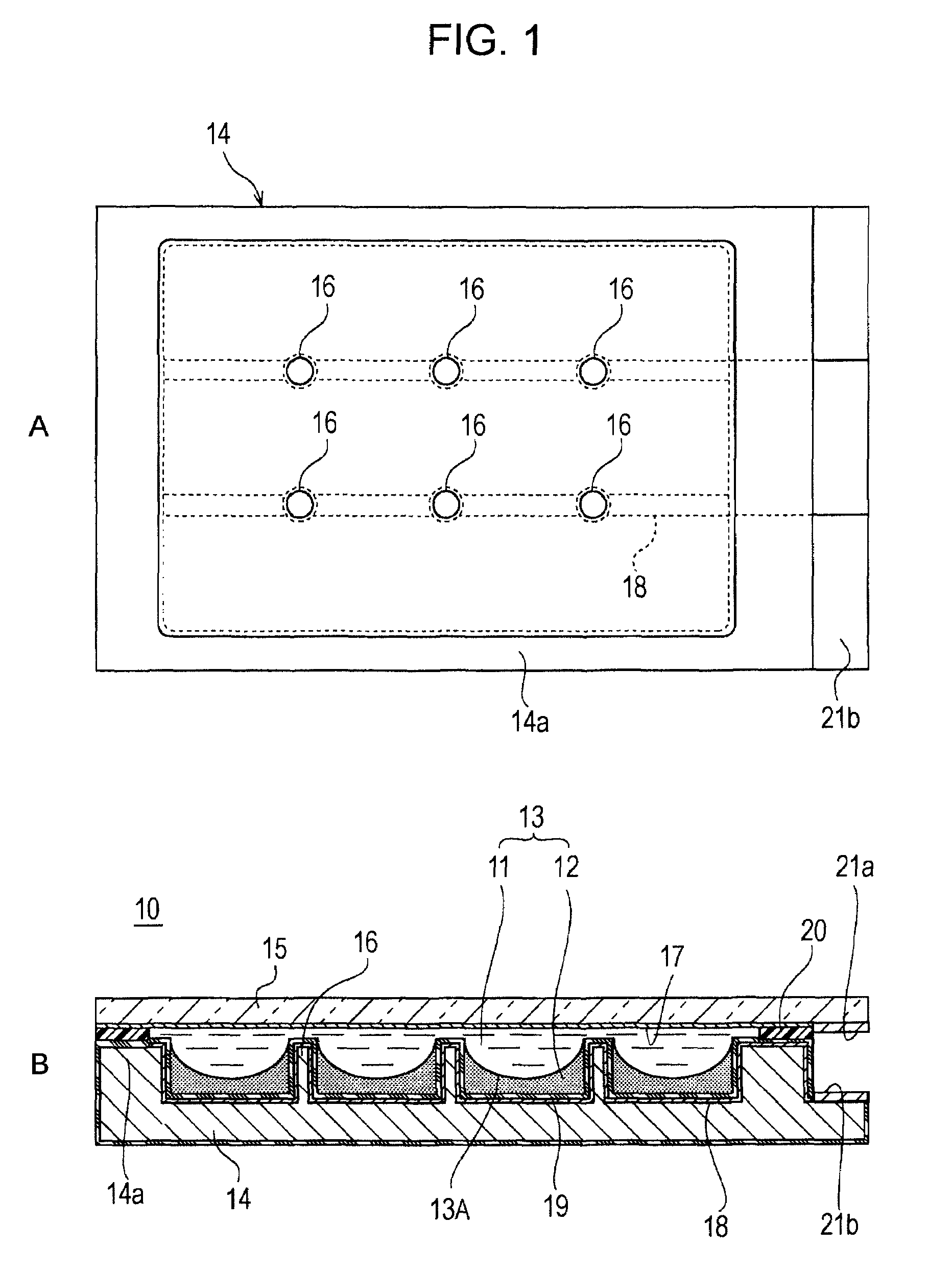
[0040]Part A of FIG. 1 and part B of FIG. 1 show the schematic structure of a lens array 10 according to a first embodiment of the present invention. Part A of FIG. 1 is a plan view of a common substrate 14 included in the lens array 10, and part B of FIG. 1 is a sectional view of the main part of the lens array 10. The lens array 10 according to the present embodiment includes a plurality of lens elements 13 in which lens surfaces 13A are formed by interfaces between first liquid 11 that is conductive and second liquid 12 that is insulative. The lens array 10 is used in, for example, an illuminating optical system, and is structured as a varifocal lens which arbitrarily varies a focal length of light that passes through the lens array 10.

[0041]Transparent conductive liquid is used as the first liquid 11. For example, polar liquid such as water, electrolyte (aqueous solution of electrolyte such as potassium chloride, sodium chloride, and lithium chloride), alcohols, such as methyl a...

second embodiment

[0069]Part A of FIG. 5 and part B of FIG. 5 show a second embodiment of the present invention. The present embodiment differs from the above-described first embodiment in that the projections which section the areas in which individual lens elements are formed has a linear shape. Here, in the figure, components corresponding to those in the above-described first embodiment are denoted by the same reference numerals, and detailed explanations thereof are omitted.

[0070]Part A of FIG. 5 is a plan view of a common substrate 14 which forms a lens array, and shows an example in which linear projections 26 are arranged in a two-dimensional grid pattern so that twelve rectangular lens-element forming areas in total are sectioned along three rows and four columns between the projections 26 adjacent to each other. Passages 27 for allowing liquid communication between the adjacent lens elements are formed in the projections 26. Although the passages 27 are formed between the projections 26 tha...

third embodiment

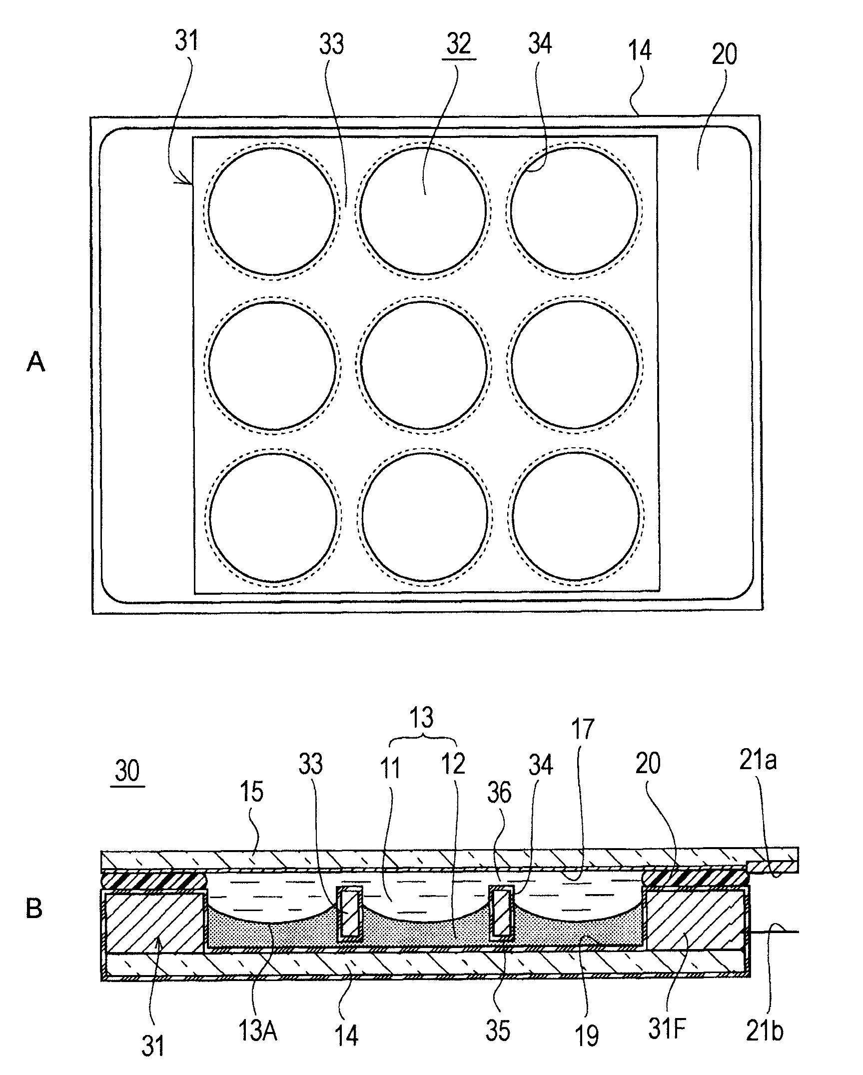
[0073]Part A of FIG. 6 and part B of FIG. 6 show the schematic structure of a lens array 30 according to a third embodiment of the present invention. Part A of FIG. 6 is a plan view showing the inner structure of the lens array 30, and part B of FIG. 6 is a sectional view of the main part of the lens array 30. Here, in the figure, components corresponding to those in the above-described first embodiment are denoted by the same reference numerals, and detailed explanations thereof are omitted.

[0074]Similar to the above-described first embodiment, a plurality of lens elements 13 including first liquid 11 and second liquid 12 are two-dimensionally arranged in a liquid chamber that is formed between a common substrate 14 and a lid body 15. Here, in the present embodiment, the common substrate 14 is formed of a transparent plate member having a flat front surface and a flat back surface, similar to the lid body 15.

[0075]In the present embodiment, a perforated plate 31 is disposed between...


PUM


Abstract

A lens array capable of making the characteristics of lens elements uniform is provided. A lens array 10 according to the present invention includes first liquid 11 that is conductive, second liquid 12 that is insulative and that has a refractive index different from that of the first liquid, and a plurality of lens elements 13 forming lens surfaces 13A at an interface between the first liquid 11 and the second liquid 12. The lens surfaces 13A of the lens elements 13 reversibly vary in accordance with output control of an applied voltage. The lens array is structured such that the adjacent lens elements 13 liquidly communicate with each other, whereby differences in the amounts of the first liquid 11 and the second liquid 12 between the lens elements can be avoided and the lens characteristics can be made uniform.

Description

[0001]This application is a 371 U.S. National Stage filing of PCT / JP2007 / 064049, filed on Jul. 10, 2007, which claims priority to Japanese Patent Application Number 2006-188781 filed at the Japanese Patent Office on Jul. 10, 2006, and Japanese Patent Application Number 2006-34595 filed at the Japanese Patent Office on Dec. 19, 2006, all of which are incorporated herein by reference.TECHNICAL FIELD[0002]The present invention relates to a lens array which utilizes electrowetting effect (electrocapillarity).BACKGROUND ART[0003]Recently, the development of optical elements utilizing the electrowetting effect has progressed. The electrowetting effect is a phenomenon in which, when a voltage is applied between conductive liquid and an electrode, energy at a solid-liquid interface between the surface of the electrode and the liquid changes and the shape of the liquid surface changes accordingly.[0004]Part A of FIG. 14 and part B of FIG. 14 are principle diagrams illustrating the electrowet...

Claims


Application Information

Patent Timeline
Patent Type & Authority Patents(United States)
IPC IPC(8): G02B1/06G02B3/12
CPCG02B3/0056G02B26/005G02B3/14
Inventor TAKAI, YUICHI
Owner SONY CORP
Why Eureka
Try Eureka