High efficiency RF transmitter system using non-linear amplifiers

a non-linear amplifier and transmitter technology, applied in the field of transmitters, can solve the problems of limiting the efficiency of the transmitter to the inherent efficiency, no way to improve efficiency, and the greatest operating cost of the base station is the cost of the electrical energy consumed by the amplifier of the transmitter, so as to achieve good linearity and improve efficiency.

Inactive Publication Date: 2011-05-31
BIRAFANE AHMED
View PDF13 Cites 10 Cited by
  • Summary
  • Abstract
  • Description
  • Claims
  • Application Information

AI Technical Summary

Benefits of technology

[0015]A transmitter system, particularly one suitable as a radio frequency or microwave (hereinafter, collectively “RF”) transmitter for wireless communication of amplitude modulated (“AM”) input signals, has a signal separator that decomposes the time-varying AM input signal S into two phase modulated envelope signals S1 and S2, with phase angle θ. The envelope signals S1 and S2 are amplified by at least one non-linear amplifiers in 2n+2 parallel branches (n=0, 1, 2, . . . ). The amplified signal envelopes S1 and S2 from both groups of n+1 branches are summed at a hybrid combiner to produce an output signal Sout that is the same as the input signal Sin, but amplified substantially linearly, and with good efficiency.
[0021]The analog part in the second solution is characterized by only two branches (as in a conventional LINC system), with each of these branches formed by an up converter (or mixer) and an RF amplifier. The output signals of the two branches are added by using a hybrid combiner. In this second solution, the two output signals S1, S2 present (i) a variable envelope for certain levels of signal, where (0<θ21θk, 1≦k≦n) and (ii) a constant envelope signals for other levels, where θk<θ<θn, 0n=90 degrees. The system of this second solution gives good linearity using a predistortion function in the signal processing circuit.
[0028]The third solution uses a combination of the first and second solutions. In the same way as the first solution, one chooses the number (2n+2) of branches to be used. The input signal is decomposed to a variable envelope for certain values of the input signal amplitude, instead of a constant envelope. For small values of the input signal amplitude, the input signal is decomposed to the constant envelope signal as in the first solution. For each value of the input signal only two branches are turning on, providing high efficiency of the system. This system yields an increased efficiency over the solutions one and two, and the linearity is good.

Problems solved by technology

The greatest operating cost of a base station is the cost of the electrical energy consumed by the amplifiers of the transmitter.
Use of a single power amplifier, e.g. class A, limits the efficiency of the transmitter to the inherent efficiency of the amplifier, and there is no way to improve the efficiency.
A digital modulation system is also known, but it requires a back off of about 5 dB PA (Power Amplifier), which introduces distortion.
A standard hybrid combiner, i.e., one matched at all ports with high isolation between its two branches, gives excellent linearity, but it degrades the efficiency of the LINC transmitter system.
With such signals applied to known LINC systems, the combining structure degrades the efficiency.

Method used


Image

  • High efficiency RF transmitter system using non-linear amplifiers
  • High efficiency RF transmitter system using non-linear amplifiers
  • High efficiency RF transmitter system using non-linear amplifiers

Examples


second embodiment

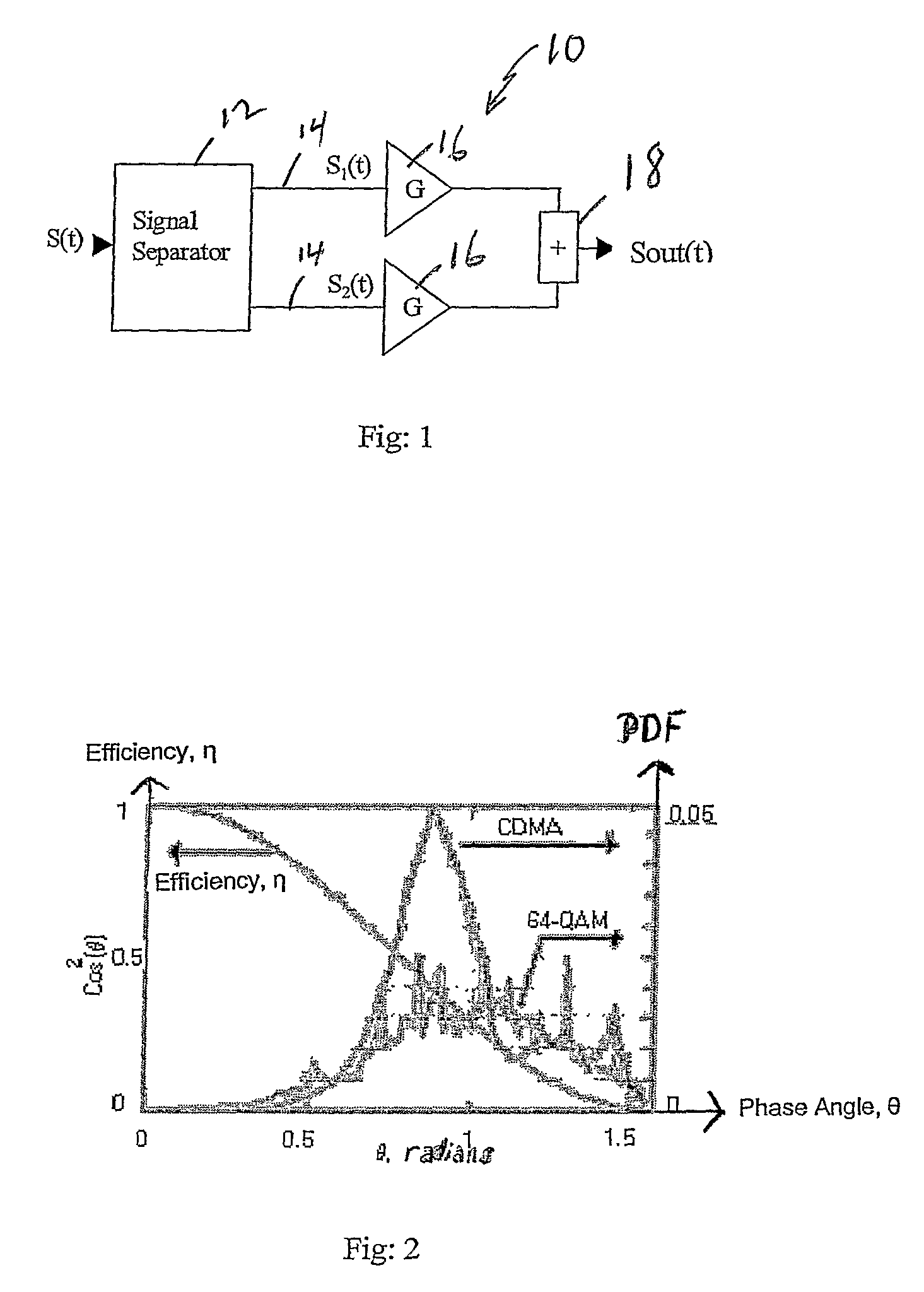
[0085]the present invention does not use an additional stage or stages of amplifiers and associated branches. It uses only two non-Ainear RF amplifiers. Each RF amplifier is used in one branch; consequently there are only two branches (FIG. 1) as in the classic UINC structure. The decomposition of signal, however, is not the same as that developed in the classic LINC. The two RF amplifiers 16, 16 are operated generally at high efficiency (class B, C, . . . ), characterized by a non-constant power gain, and with non-linearity at output.

[0086]This invention uses each RF amplifier 16, 16 in its non-linear operation zone. The power output of a suitable RF amplifier with Class F as a function of input power to the amplifier is shown in FIG. 9.

[0087]In a first operating zone, from where the output power where the amplifier is highly efficient to some dB of back off, the decomposition of the input signal S(t) by the separator 12 operates to separate the input signal S into two identical si...

embodiment 2

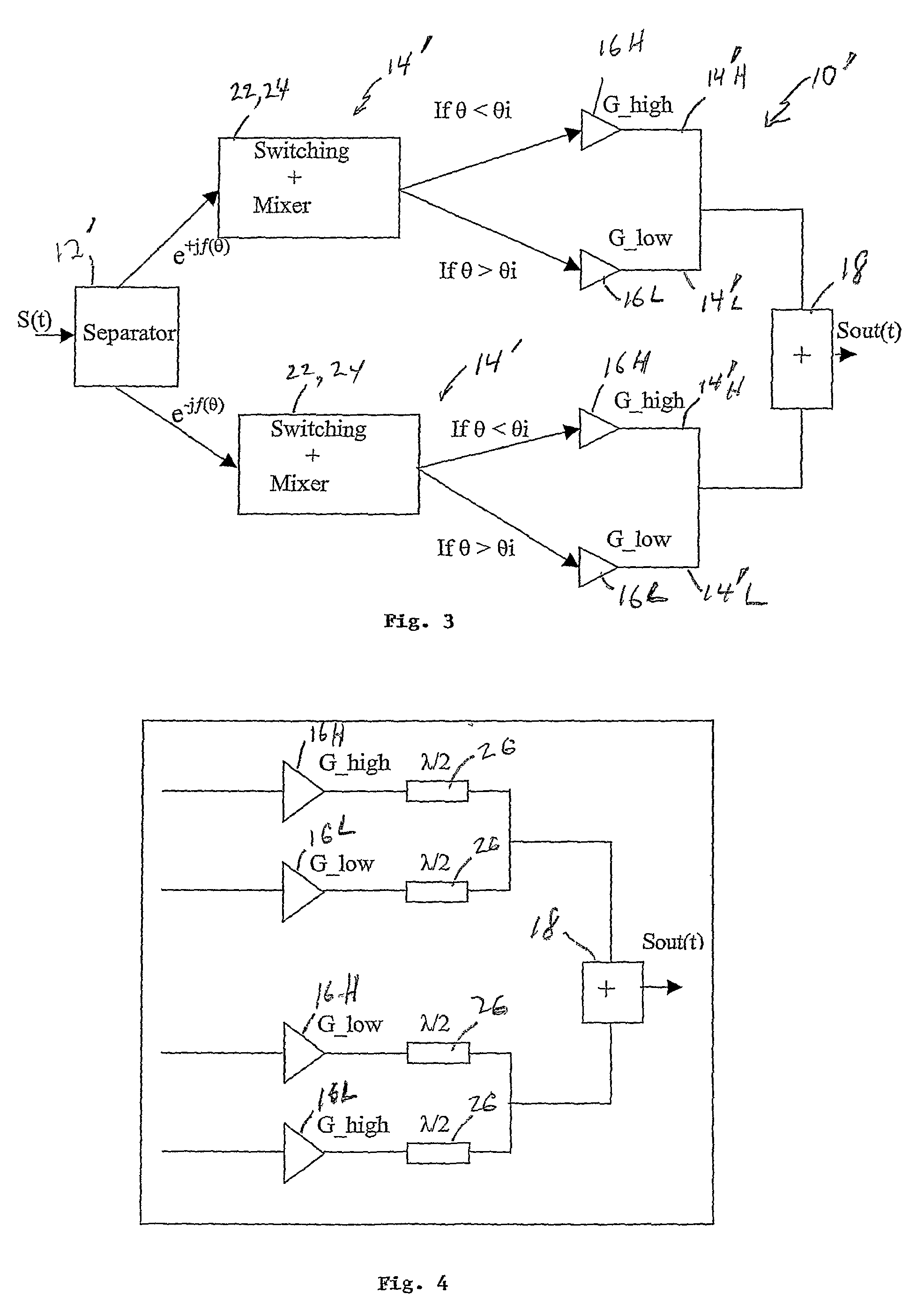
[0098]The third solution or embodiment of this invention applies the two solutions 1 and 2 described above simultaneously. That means, in the multistage solution (FIG. 7) each RF amplifier 16H, 16L(1) . . . 16L(n−1) is used with a non-constant envelope, instead of a constant envelope. In the multi-stage RF amplifiers with G_high, G_low_i (i=1 to n−1), one applies the second solution in the condition 0—1) one applies the second solution completely, i.e. one considers the second part of signals described above with respect to solution /

[0099]The new average efficiency ηavg is:

[0100]ηAve=ηhigh⁢∑θ⁢⁢k<θ⁢⁢1⁢[Idchigh⁢_maxIdchigh⁢_k]⁢Cos2⁡(θ⁢⁢k)⁢pk+∑i=1n-1⁢ηlow⁢_⁢⁢i⁡[∑θ⁢⁢i+1>θ⁢⁢j>θ⁢⁢i⁢[Idclow⁢_⁢⁢i⁢_maxIdclow⁢_⁢⁢i⁢_k]⁢pj·Cos2⁡(θ⁢⁢j)]+ηlow⁢_⁢⁢n⁡[∑90>θ⁢⁢j>θ⁢⁢n⁢pj·Cos2⁡(θ⁢⁢j)](25)

[0101]In this embodiment, one can optimize (25) to find a best value of θi i=1 to n to obtain a best efficiency.

[0102]Using an RF transmitter according to the present invention, one can achieve a signific...


PUM


Abstract

An RF transmitter with improved efficiency and good linearity decomposes an input AM signal into two signal envelopes with phased modulation at a phase angle θ. The transmitter has three principal embodiments. A first solution uses at least one added RF amplifier for each decomposed signal envelope with one or more amplifiers having a low gain compared to that of a high gain amplifier in another branch for the same signal envelope. A phase angle θi is determined that corresponds to a switching on two of the 2n+2 total branches, n=0, 1, 2, . . . . A second solution uses the same general schematic architecture as the classic LINC system that requires only two RF amplifiers, but uses a different decomposition because the two RF amplifiers are used in their nonlinear zone. The decomposed signal envelopes can be variable. The amplified output signal allows the combiner to be used at 100% efficiency in major part of signal. The third solution combines the first and second solutions.

Description

CROSS-REFERENCE TO RELATED APPLICATION[0001]This application claims the benefit of U.S. provisional application No. 60 / 685,145 filed May 27, 2005, the disclosure of which is incorporated herein by reference.BACKGROUND OF THE INVENTION[0002]This invention relates to transmitters. More specifically, it relates to transmitting apparatus and methods using non-linear amplifiers to produce linear amplification of an input signal, particularly one with high peak-to-average power, with an improved efficiency.[0003]Modern wireless communication systems have a need for transmitters with an improved efficiency while avoiding distortion. The greatest operating cost of a base station is the cost of the electrical energy consumed by the amplifiers of the transmitter. Any significant improvement in efficiency over the known systems presents a like significant advantage in energy and cost savings.[0004]Use of a single power amplifier, e.g. class A, limits the efficiency of the transmitter to the in...

Claims


Application Information

Patent Timeline
Patent Type & Authority Patents(United States)
IPC IPC(8): H01Q11/12H04K3/00
CPCH03F1/0205H03F1/0277H03F1/0294H03F3/211H03F3/24H03F3/72H03F3/602H03F2200/204H03F2200/423H03F2200/451H03F2203/21109H04B1/04
Inventor BIRAFANE, AHMED
Owner BIRAFANE AHMED
Why Eureka
Try Eureka