Non-slip transmissions particularly useful as continuously-variable transmissions and transmission members thereof

a transmission and non-slip technology, applied in the direction of gearing, driving chains, hoisting equipments, etc., can solve the problems of continuous-variable transmissions, slippage between the contact surfaces, rapid wear of the contact surfaces, etc., and achieve low friction loss, high durability, and eliminate slippage

Inactive Publication Date: 2011-06-07
CVTRON LTD
View PDF124 Cites 7 Cited by
  • Summary
  • Abstract
  • Description
  • Claims
  • Application Information

AI Technical Summary

Benefits of technology

[0011]An object of the present invention is to provide a transmission, and particularly a continuously-variable transmission (CVT), having advantages in some or all of the above respects. More particularly, an object of the invention is to provide a continuously-variable transmission which is capable of driving large loads, which substantially eliminates slippage, which provides a sufficient area of contact between the engaged surfaces, and / or, which is characterized by low friction losses and high durability. Another object the invention is to provide a CVT having the capability of an infinitely-variable transmission (IVT). A further object is to provide a novel transmission members particularly useful in such transmission systems.
[0013]A “pitch” of an array of projections and depressions is the distance between common points on the array. In the CVT of the present application, the pitch of the surface formed with the projections and depressions is the same for every cross-section of the surface perpendicular to the rotary axis; this distinguishes from the conical surfaces of many of the prior-art CVT systems, and thereby, avoids many of the drawbacks of the prior art systems as briefly described above.
[0016]As will be described more particularly below, the foregoing features enable continuously-variable transmissions to be provided having no significant slippage or friction despite the variations in spacing of the coupling elements produced with the variations in diameters of the respective transmission member. The foregoing features further provide a large area of contact between the coupling elements, minimal energy losses, and a capability of high torque transfer. In addition, such systems avoid the creation of undue differential stresses in the coupling elements along the contact lines, characteristic of continuously-variable transmission (CVT) systems having projections and depressions on conical surfaces. Such a transmission is also capable of being designed as an infinitely-variable transmission (IVT) having a large range of possible transmission ratios, even down to a zero velocity on the output shaft without the need for a clutch.
[0021]4. maintain a uniform pitch across the contact line with the topography, thus ensuring equal speed of motion and equal pressure between the members,
[0030]According to yet another aspect of the present invention, there is provided a variable-diameter rotary wheel particularly useful in such a continuously-variable transmission, comprising: an inner pair of spaced discs joined together by a first ring, and an outer pair of spaced discs joined together by a second ring coaxial with the first ring; one pair of discs being formed with a plurality of radially-extending straight slots, and the other pair of discs being formed with a plurality of radially-extending curved slots; and a plurality of pins having their opposite ends received in both a straight slot and in a curved slot of the respective discs, such that rotation of one of the discs in each pair with respect to the other disc in the pair causes the pins to move radially with respect to the discs, according to the direction of rotation, thereby changing the effective diameter of the rotary member.
[0031]According to a still further aspect of the invention, there is provided a continuously-variable transmission, comprising: first and second transmission members each having a group of coupling elements successively engageable to couple the transmission members for movement together; at least one of said transmission members being a rotary member rotatable about a rotary axis; at least one of said groups of coupling elements being radially displaceable towards and away from the rotary axis to change the conversion ratio of said transmission; the coupling elements of one of said groups being of a fixed configuration defining projections alternating with depressions each of a fixed configuration; the coupling elements of the other of said groups being of a self-adaptive configuration, each individually movable in opposite directions to adapt itself to the configuration of said fixed configuration coupling elements in all displacement positions of the radially-displaceable coupling elements; said rotary member including an inner pair of spaced discs joined together by a first ring, and an outer pair of spaced discs joined together by a second ring coaxial with said first ring; one pair of discs being formed with a plurality of radially-extending straight slots, and the other pair of discs being formed with a plurality of radially-extending curved slots; the opposite ends of each of said of coupling elements of said rotary member being received in both a straight slot and in a curved slot of the respective discs such that rotation of one of said discs in each pair with respect to the other disc in the pair causes said coupling elements to move radially with respect to said discs, according to the direction of rotation, thereby changing the effective diameter of the rotary member.

Problems solved by technology

A main problem in many types of existing continuously-variable transmissions (CVTs) is slippage between the contacted surfaces.
Slippage causes rapid wear of the contact surfaces, together with energy losses and low efficiency.
These problems become more serious as the transmitted torque increases.
For this reason, continuously-variable transmissions currently find little use in machines requiring high torque transmission, such as medium and heavy vehicles and industrial machinery.
The high coefficient of friction and the high pressure between the surfaces are intended to prevent slippage, but even this is insufficient in certain cases.
Such systems may be adequate for the transmission of small torques, but are generally considered to be uneconomical and inefficient when applied to the transmission of high torques.
Special cumbersome means are therefore necessary to overcome this problem, if possible at all.
This method requires the coupling elements to converge to their operational position through a cumbersome back and forth trajectory in which they slide on and collide with other parts of the topography in a non-matching angles of contact, creating increasing friction and bending moments.
However, the conical structure of the system of this patent creates a non-uniform pitch and a non-uniform speed along the line of contact between the coupling element and the topography, resulting in the creation of undue differential stresses, bending moments, and slippage between the coupled elements.
In practice, this system implies a small number of small lines of contact—thus a limited transmission of moments.

Method used


Image

  • Non-slip transmissions particularly useful as continuously-variable transmissions and transmission members thereof
  • Non-slip transmissions particularly useful as continuously-variable transmissions and transmission members thereof
  • Non-slip transmissions particularly useful as continuously-variable transmissions and transmission members thereof

Examples


Embodiment Construction

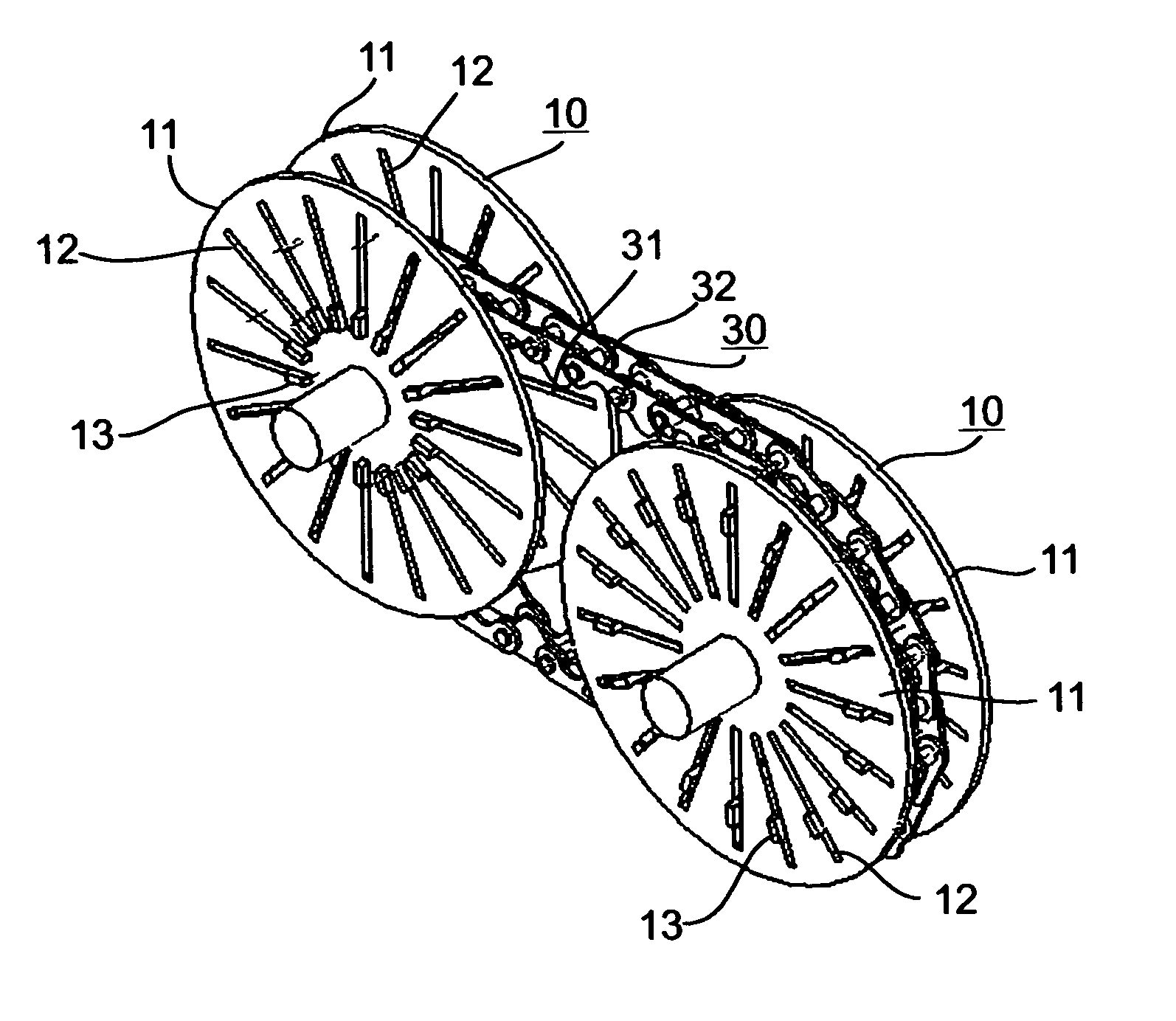
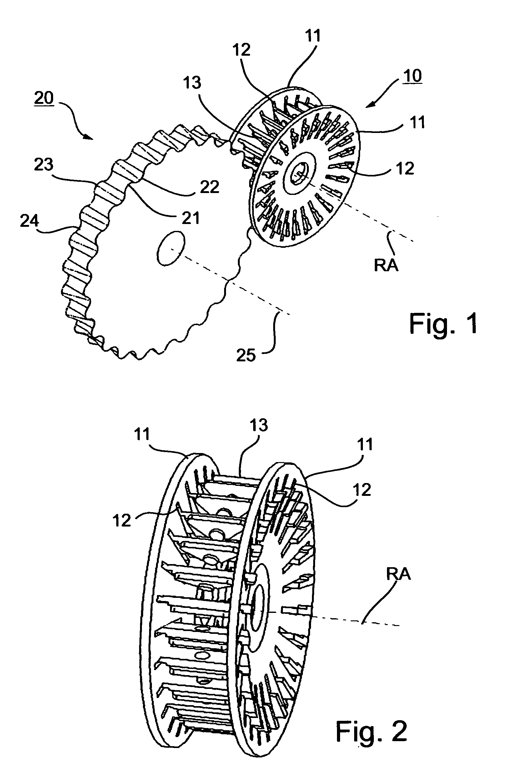
[0119]FIGS. 1-4 illustrate a continuously-variable transmission CVT constructed in accordance with the invention and including two rotary members, namely a variable-diameter toothed wheel 10 rotatable about rotary axis RA, and a fixed-diameter toothed wheel 20 rotatable about its rotary axis 25, parallel to rotary axis RA.

[0120]The variable-diameter toothed wheel 10 includes a pair of axially-spaced discs 11, 11, formed with a plurality of radially-extending slots 12, 12, receiving the opposite ends of an annular array of coupling elements 13.

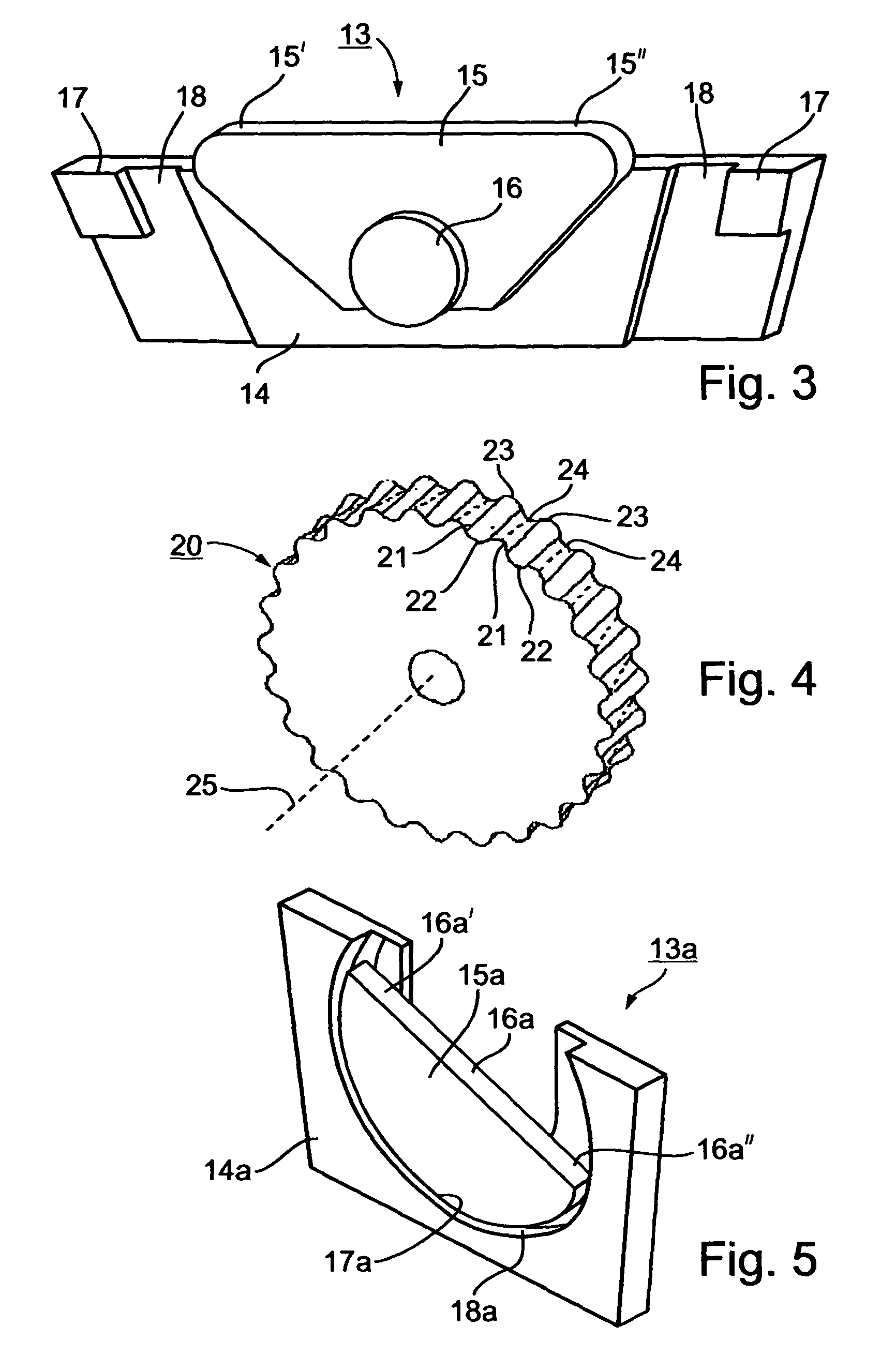
[0121]The construction of each of the coupling elements 13 is more particularly illustrated in FIG. 3. It includes a mounting plate 14 having its opposite ends slidably received within slots 12, 12 of the wheel discs 11, 11. It also includes a contact plate 15 pivotally mounted at 16 to the mounting plate. The opposite ends of the mounting plate 14 are thickened, as shown at 17, to define tracks 18 to be slidably received within the slots 12, 1...


PUM


Abstract

A continuously-variable transmission includes two transmission members each having coupling elements engageable to couple the transmission members for movement together. At least one of the transmission members is a rotary member rotatable about a rotary axis; and at least one of the groups of coupling elements is radially displaceable towards and away from the rotary axis to change the conversion ratio of the transmission. The coupling elements of one group on one transmission member are of a fixed configuration defining projections alternating with depressions each of a fixed configuration formed on a surface of the transmission member between opposite side faces and having the same pitch for every cross section of the surface perpendicular to the mentioned rotary axis. The coupling elements of the other group are of a self-adaptive configuration, each movable in opposite directions to adapt itself to the configuration of the fixed-configuration coupling elements in all displacement positions of the radially-displaceable coupling elements and to effect a non-slip coupling therewith.

Description

FIELD AND BACKGROUND OF THE INVENTION[0001]The present invention relates to non-slip transmissions particularly useful as continuously-variable transmissions, and also to transmission members included therein.[0002]The term “continuously variable transmission” (CVT) is used herein in its normal and accepted sense, namely as a transmission in which the ratio of the rotational speeds of two shafts can be varied continuously, without break or interruption, within a given range, to provide an infinite number of possible ratios”. A “continuously variable transmission” (typically using rubber belts and pulleys) is to be sharply distinguished from a “step-variable transmission” (typically including gears), which provides a finite number of possible ratios according to the steps (e.g. gear teeth), rather than an infinite number of possible ratios without break or interruption.[0003]A main problem in many types of existing continuously-variable transmissions (CVTs) is slippage between the co...

Claims


Application Information

Patent Timeline
Patent Type & Authority Patents(United States)
IPC IPC(8): F16H55/00F16H7/06F16H7/00F16G1/28F16H1/06F16G13/02F16G13/06F16H9/10F16H9/24F16H55/12F16H55/30F16H55/38F16H55/52F16H55/54
CPCF16G13/02F16H55/54F16H9/24F16H3/42
Inventor SIMAN-TOV, RAN
Owner CVTRON LTD
Why Eureka
Try Eureka