Unlock instant, AI-driven research and patent intelligence for your innovation.

Membrane electrode assembly prepared by direct spray of catalyst to membrane

a technology of membrane and catalyst, applied in the direction of electrode manufacturing process, electrochemical generator, cell components, etc., can solve the problems of high cost of eptfe substrate, difficult cleaning step, and relatively high cost of mea manufacturing, so as to improve mea performance and strengthen the catalyst layer

Active Publication Date: 2011-06-07
GM GLOBAL TECH OPERATIONS LLC
View PDF10 Cites 3 Cited by
  • Summary
  • Abstract
  • Description
  • Claims
  • Application Information

AI Technical Summary

Benefits of technology

[0019]Additional processing steps can subsequently be performed to improve MEA performance. For example, the MEA can be soaked in a water bath or boiled in water, the MEA can be soaked in sulfuric acid bath to remove excess solvent and ensure protonation, and the MEA can be hot-pressed to remove excess solvent and to compress and possibly strengthen the catalyst layer.

Problems solved by technology

MEAs are relatively expensive to manufacture and require certain conditions for effective operation.
However, the ePTFE substrate is expensive and not reusable.
Additionally, the ePTFE substrate stretches, deforms and absorbs solvents making a cleaning step very difficult.
MEAs prepared by the above described decal substrate transfer processes have exhibited failure along the catalyst edge.
This failure typically corresponds to the edge of the decal substrate during the hot-pressing step.
This translates to a possible weakening of the membrane along the catalyst edges.
However, this MEA fabrication process also suffers from membrane failure proximate the edge of the catalyst layer.
Therefore, gases being transported through the diffusion media react directly with the membrane instead of the catalyst, possibly causing combustion as a result of the interaction of hydrogen and oxygen, which also may damage the membrane.
Also, in the CCDM process, the ionomer in the catalyst tends to be adsorbed into the diffusion media because of its porosity resulting in less ionomer that is available to electrically couple the catalyst layer to the membrane when the CCDM is hot pressed to the membrane.
Therefore, there is a reduction in MEA performance.
In addition, the processes discussed above involve wasting catalyst and ionomer, wasting material that isn't in the final MEA, and several processing steps that take up time and resources, such as die cutting, hot pressing and peeling off of decal substrates.

Method used


Image

  • Membrane electrode assembly prepared by direct spray of catalyst to membrane
  • Membrane electrode assembly prepared by direct spray of catalyst to membrane
  • Membrane electrode assembly prepared by direct spray of catalyst to membrane

Examples


Embodiment Construction

[0024]The following discussion of the embodiments of the invention directed to a process for spraying a catalyst on a proton conducting membrane of an MEA is merely exemplary in nature, and is in no way intended to limit the invention or its applications or uses.

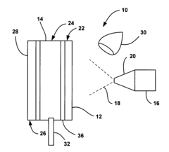
[0025]The present invention is a simplified method of fabricating an MEA for a PEMFC that reduces costs, materials and manufacturing resources, and also increases MEA durability. FIG. 1 is a plan view of a system 10 for fabricating an MEA 24, according to the invention. The MEA 24 includes a polymer electrolyte proton conducting membrane 14 in its protonated form (H+), such as a perflourinated membrane. The system 10 includes a sprayer 16 that emits a spray of catalyst ink 18 through a suitable nozzle 20 onto the membrane 14 to form a catalyst layer 12. In one embodiment, the sprayer 16 is an airbrush gun to deposit the catalyst layer 12 on the membrane 14 to the desirable thickness. In one embodiment, the catalyst ink 18 is...


PUM

PropertyMeasurementUnit
thicknessaaaaaaaaaa
thicknessaaaaaaaaaa
compressaaaaaaaaaa

Abstract

A technique for fabricating an MEA. The technique includes providing a polymer electrolyte proton conducting membrane, and then spraying a catalyst ink directly on the membrane to form a catalyst layer. In one embodiment, the catalyst ink includes the proper ionomer to carbon ratio, such as 0.8 / 1, for the desired fuel cell performance. In another embodiment, the catalyst ink includes too little ionomer for the proper ionomer to carbon ratio for the desired fuel cell performance. An ionomer layer is sprayed on the membrane before the catalyst layer to provide the proper final ionomer to carbon ratio.

Description

BACKGROUND OF THE INVENTION[0001]1. Field of the Invention[0002]This invention relates generally to a membrane electrode assembly (MEA) for a proton exchange fuel cell (PEMFC) and, more particularly, to an MEA for a PEMFC, where an anode catalyst layer and / or a cathode catalyst layer of the MEA is sprayed on a proton conducting membrane.[0003]2. Discussion of the Related Art[0004]Hydrogen is a very attractive fuel because it is clean and can be used to efficiently produce electricity in a fuel cell. The automotive industry expends significant resources in the development of hydrogen fuel cells as a source of power for vehicles. Such vehicles would be more efficient and generate fewer emissions than today's vehicles employing internal combustion engines.[0005]A hydrogen fuel cell is an electro-chemical device that includes an anode and a cathode with an electrolyte therebetween. The anode receives hydrogen gas and the cathode receives oxygen or air. The hydrogen gas is disassociated ...

Claims


Application Information

Patent Timeline
Patent Type & Authority Patents(United States)
IPC IPC(8): H01M8/10B05D5/12H01M4/88H01M4/96
CPCH01M4/881H01M4/886H01M4/8882H01M4/8817H01M4/0407Y02E60/50Y02E60/10
Inventor YAN, SUSAN G.DOYLE, JOHN C.
Owner GM GLOBAL TECH OPERATIONS LLC