Power inverter

a power inverter and power technology, applied in the field of power inverters, can solve the problems of increasing equipment size and increasing heat release value, and achieve the effect of reducing the size of the power inverter

Active Publication Date: 2011-06-07
HITACHI ASTEMO LTD
View PDF12 Cites 43 Cited by
  • Summary
  • Abstract
  • Description
  • Claims
  • Application Information

AI Technical Summary

Benefits of technology

[0008]For a pure electric vehicle driven by motor power without using a combustion engine and a hybrid electric vehicle using a combustion engine together with a motor, there is a demand for an increase in the ratio of the cabin to the entire vehicle capacity for better riding comfort. In order to mount a control unit in a smallest possible space, downsizing of the control unit is demanded. There is also a demand for a downsized power inverter electrically connected with a rotating electric machine for vehicle. However, trend of on-board rotating electric machines is toward increasing power resulting in a larger heat release value than in early stages of development. Moreover, trend for larger power induces the use of high voltages, increasing the size of equipment. For this reason, the size of power inverters is steadily increasing.
[0009]A main object of the present invention is to provide a power inverter which prevents an increase in size.
[0029]An effect of the present invention is that a power inverter can be downsized.

Problems solved by technology

However, trend of on-board rotating electric machines is toward increasing power resulting in a larger heat release value than in early stages of development.
Moreover, trend for larger power induces the use of high voltages, increasing the size of equipment.

Method used


Image

  • Power inverter
  • Power inverter
  • Power inverter

Examples


Embodiment Construction

[0046]The following explains embodiments of the power inverter by the present invention with reference to the accompanying drawings.

(Electric Vehicle 100)

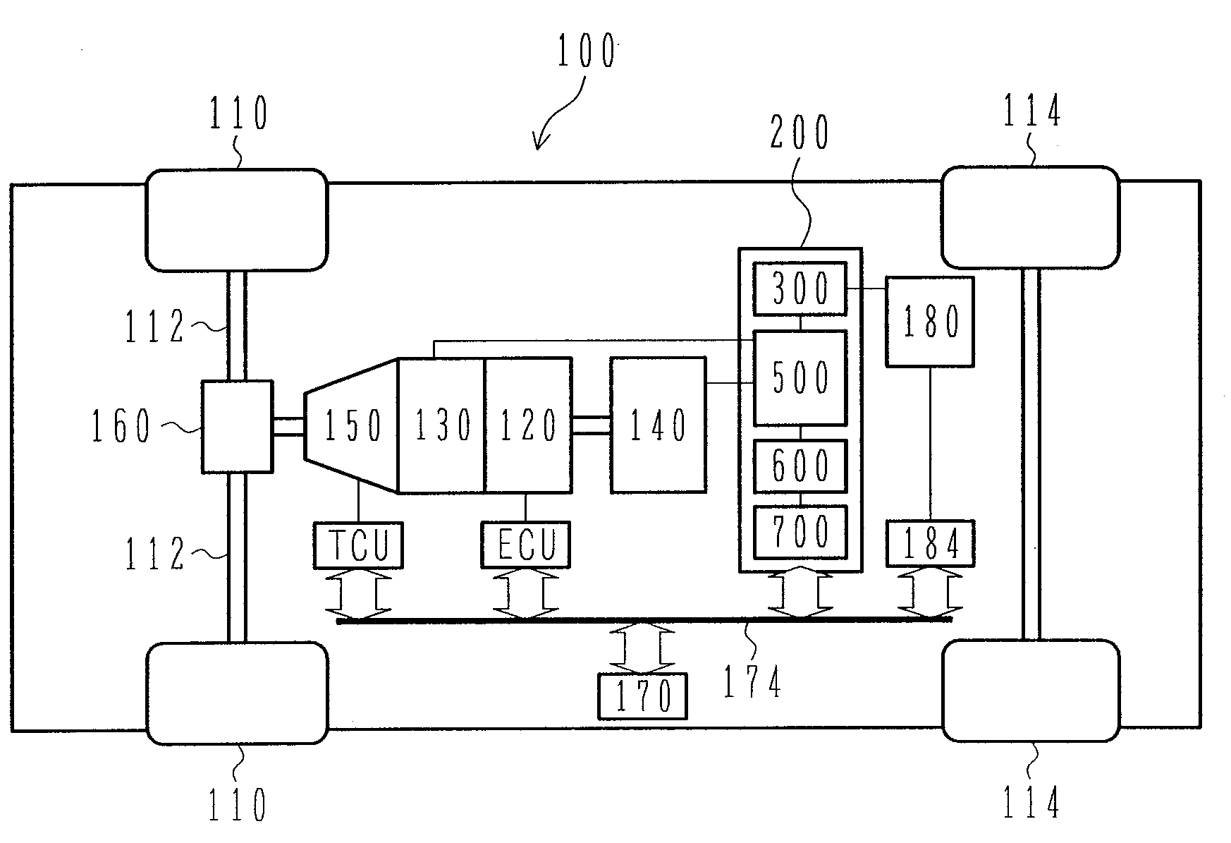
[0047]FIG. 1 is a schematic diagram showing a hybrid electric vehicle which can mount the power inverter according to an embodiment of the present invention. A power inverter 200 according to the present invention can obviously be applied also to a pure electric vehicle, and many of basic configurations and operations are common to a hybrid electric vehicle and a pure electric vehicle. Therefore, the following explains some embodiments of hybrid electric vehicle as a representative case.

[0048]A hybrid electric vehicle 100 having front wheels 110 and rear wheels 114 is provided with an engine 120, a first rotating electric machine 130, a second rotating electric machine 140, and a battery 180 which supplies high-voltage DC power to the first rotating electric machine 130 and second rotating electric machine 140. Actually, a battery ...


PUM


Abstract

A power inverter comprises at least a box-shaped housing; and a power module, a smoothing capacitor, a base plate made of a flat plate, and a rotating electric machine control circuit board arranged in order in the housing. The base plate is arranged with the fringes fixed to the inner wall surfaces of the housing, and the smoothing capacitor and rotating electric machine control circuit board are fixed.

Description

[0001]This application claims the benefit of priority under 35 U.S.C. §119 to Japanese Patent Application No. 2006-104922, filed Apr. 6, 2006, the disclosure of which is incorporated by reference herein in its entirety. This application is related to U.S. application Ser. No. 11 / 600,124, filed Nov. 16, 2006.BACKGROUND OF THE INVENTION[0002]1. Field of the Invention[0003]The present invention relates to a power inverter, for example, a power inverter suitable for a vehicle.[0004]2. Description of the Related Art[0005]A power inverter comprises an inverter, a smoothing capacitor connected in parallel with a DC power supply terminal of the inverter, and a control circuit which controls the inverter. The inverter has a plurality of power semiconductors, and the plurality of inverters are used as a power module in unit of a predetermined number. Therefore, the inverter comprises one or more power modules including a plurality of power semiconductors.[0006]It is known that such a power in...

Claims


Application Information

Patent Timeline
Patent Type & Authority Patents(United States)
IPC IPC(8): H05K5/04H05K7/20B60L50/16
CPCB60K6/26B60K6/405B60K6/48H02P27/06B60W10/08H02M7/003H05K7/20927B60K1/02Y02T10/6221B60K2001/003Y02T10/62
Inventor NAKAJIMA, KENICHIROHAMADA, HARUKISUZUKI, HIDEYO
Owner HITACHI ASTEMO LTD
Why Eureka
Try Eureka